Melt Pool Monitoring System and Method for Detecting Errors in an Additive Manufacturing Process

a technology of additive manufacturing and error detection, applied in the field of additive manufacturing machines, can solve the problems of scrapped parts, complex process, and low knowledge of the scientific and technical aspects of the production route, and achieve the effects of sintering or melting rate and processing parameters on the microstructural evolution of the layer manufacturing process

Active Publication Date: 2020-05-14
GENERAL ELECTRIC CO
View PDF0 Cites 5 Cited by
  • Summary
  • Abstract
  • Description
  • Claims
  • Application Information

AI Technical Summary

Benefits of technology

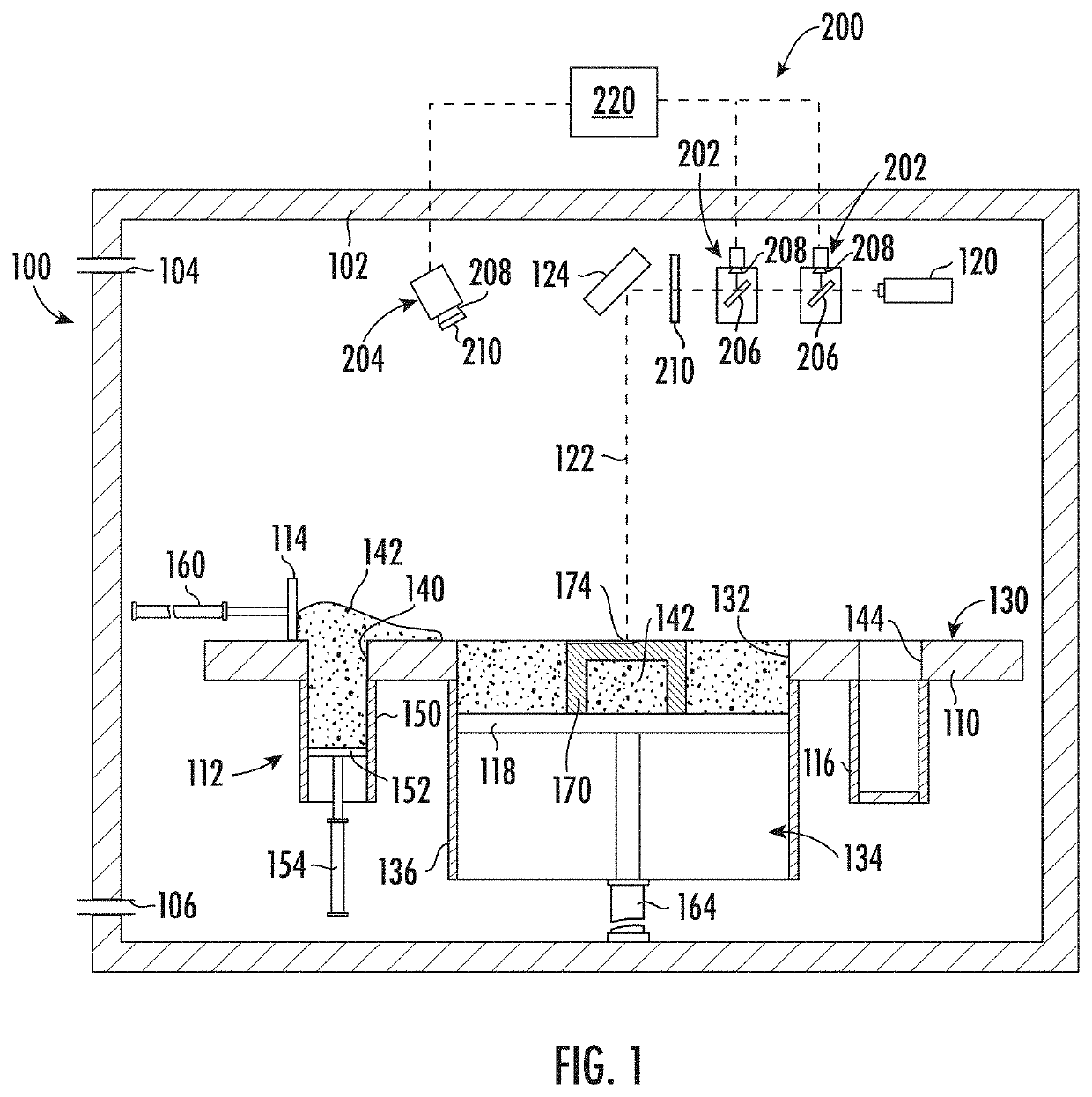
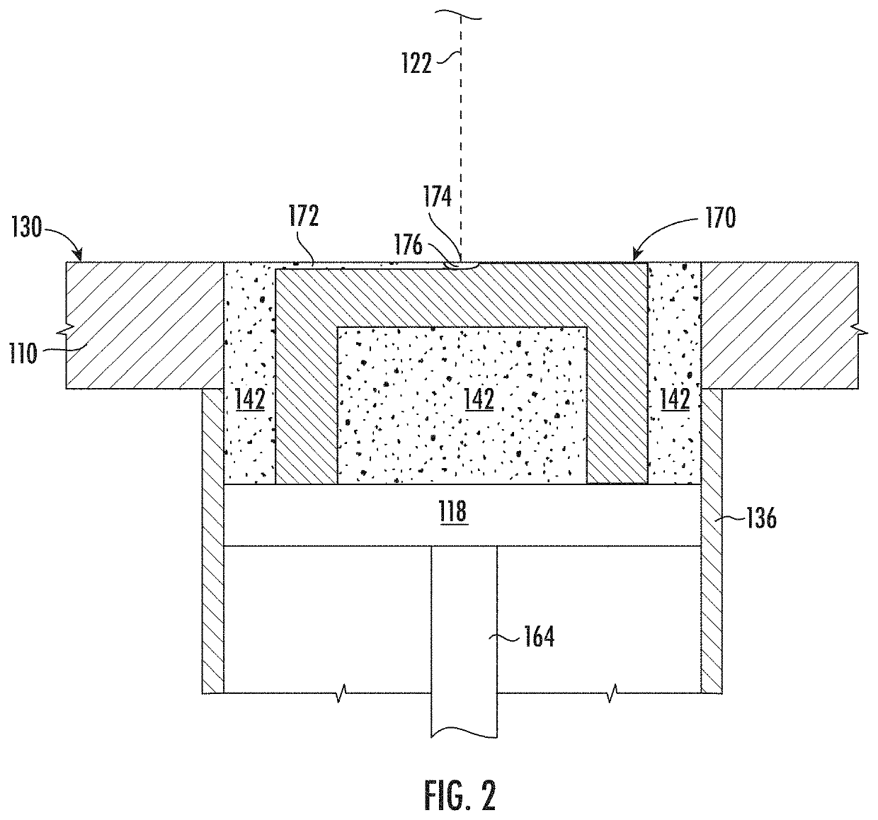
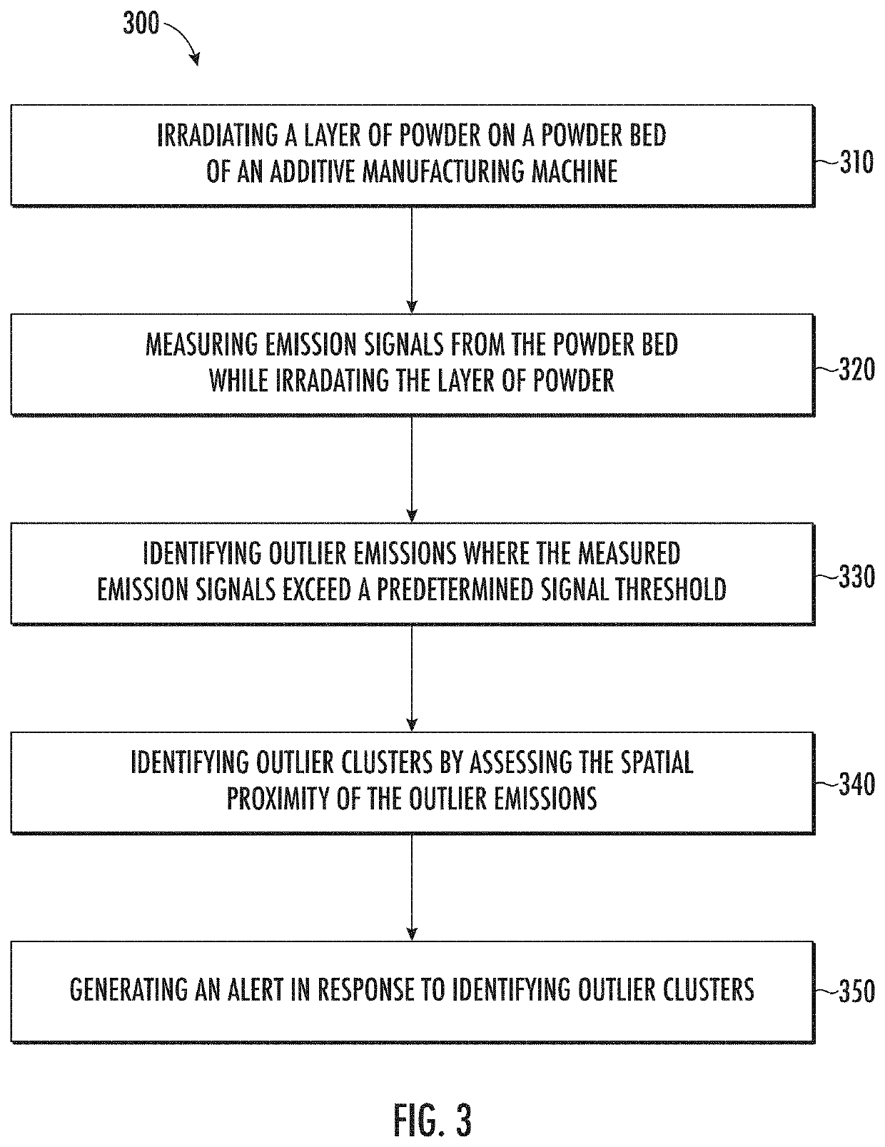
The present invention relates to a method and system for monitoring a powder-bed additive manufacturing process. The system includes an irradiation device for fusing a layer of additive material on a powder bed, and a melt pool monitoring system for measuring emission signals from the powder bed during the fusing process. The system can identify outlier emissions that exceed a predetermined signal threshold and outlier clusters with reference to the spatial proximity of the outlier emissions. The technical effect of this invention is to provide a system for early detection and identification of abnormal or outlier emissions, which can help improve the manufacturing process and prevent defective parts from being produced.

Problems solved by technology

Although the laser sintering and melting processes can be applied to a broad range of powder materials, the scientific and technical aspects of the production route, for example, sintering or melting rate and the effects of processing parameters on the microstructural evolution during the layer manufacturing process have not been well understood.
This method of fabrication is accompanied by multiple modes of heat, mass, and momentum transfer, and chemical reactions that make the process very complex.
However, most melt pool monitoring systems perform data analysis after a build is completed or are otherwise complex and delayed in identifying process issues.
Moreover, such melt pool monitoring systems are frequently not effective at identifying process faults that result in quality issues in finished parts, scrapped parts, increased material costs, and excessive machine downtime.

Method used


Image

  • Melt Pool Monitoring System and Method for Detecting Errors in an Additive Manufacturing Process
  • Melt Pool Monitoring System and Method for Detecting Errors in an Additive Manufacturing Process
  • Melt Pool Monitoring System and Method for Detecting Errors in an Additive Manufacturing Process

Examples


Embodiment Construction

[0021]Reference now will be made in detail to embodiments of the invention, one or more examples of which are illustrated in the drawings. Each example is provided by way of explanation of the invention, not limitation of the invention. In fact, it will be apparent to those skilled in the art that various modifications and variations can be made in the present invention without departing from the scope or spirit of the invention. For instance, features illustrated or described as part of one embodiment can be used with another embodiment to yield a still further embodiment. Thus, it is intended that the present invention covers such modifications and variations as come within the scope of the appended claims and their equivalents.

[0022]As used herein, the terms “first”, “second”, and “third” may be used interchangeably to distinguish one component from another and are not intended to signify location or importance of the individual components. In addition, as used herein, terms of a...


PUM

PropertyMeasurementUnit
Currentaaaaaaaaaa
Electric potential / voltageaaaaaaaaaa
Energyaaaaaaaaaa

Abstract

A system and method of monitoring a powder-bed additive manufacturing process is provided where a layer of additive powder is fused using an energy source and electromagnetic emission signals are measured by a melt pool monitoring system to monitor the print process. The measured emission signals are analyzed to identify outlier emissions and clusters of outliers are identified by assessing the spatial proximity of the outlier emissions, e.g., using clustering algorithms, spatial control charts, etc. An alert may be provided or a process adjustment may be made when a cluster is identified or when a magnitude of a cluster exceeds a predetermined cluster threshold.

Description

PRIORITY INFORMATION[0001]The present applicant claims priority to U.S. Provisional Patent Application Ser. No. 62 / 757,849 titled “Melt Pool Monitoring System and Method for Detecting Errors in an Additive Manufacturing Process” filed on Nov. 9, 2018, the disclosure of which is incorporated by reference herein.FIELD[0002]The present disclosure generally relates to additive manufacturing machines, or more particularly, to error detection systems and methods for an additive manufacturing machine.BACKGROUND[0003]Additive manufacturing (AM) processes generally involve the buildup of one or more materials to make a net or near net shape (NNS) object, in contrast to subtractive manufacturing methods. Though “additive manufacturing” is an industry standard term (ISO / ASTM52900), AM encompasses various manufacturing and prototyping techniques known under a variety of names, including freeform fabrication, 3D printing, rapid prototyping / tooling, etc. AM techniques are capable of fabricating c...

Claims


Application Information

Patent Timeline
IPC IPC(8): B23K26/342B33Y10/00B33Y30/00B33Y50/02B23K26/03B23K26/14B23K26/70B23K31/00
CPCB33Y50/02B33Y30/00B23K26/032B23K31/003B23K26/702B23K26/1464B23K26/342B33Y10/00B23K26/034G01R29/0871B28B1/001B29C64/393B33Y40/00B22F10/00B22F12/90B22F12/49B22F10/28B22F12/60B22F10/368B22F10/322B29C64/153Y02P10/25
Inventor GOLD, SCOTT ALANSPEARS, THOMAS GRAHAMANAND, AJAY KUMAR
Owner GENERAL ELECTRIC CO
Why Eureka
Try Eureka