
Wireless amagnetic heating module

a technology of amagnetic heating and wireless induction, which is applied in the direction of induction heating, electric/magnetic/electromagnetic heating, melt circulation arrangement, etc., can solve the problems of inability to establish a standard parameter with maximum efficiency common to multiple uses and applications, and the most inefficient and difficult control system. , to achieve the effect of high thermal conductivity

Active Publication Date: 2020-04-30
E WENCO SRL
View PDF0 Cites 2 Cited by
  • Summary
  • Abstract
  • Description
  • Claims
  • Application Information

AI Technical Summary

Benefits of technology

The present invention provides an amagnetic wireless heating module that can quickly heat liquids, solids, and gases in motion. The movement can be generated by the chamber around the module or the module itself. This results in a highly effective and efficient wireless module for heating and drying stationary materials or materials in transit inside enclosed spaces.

Problems solved by technology

. . The free flame is excellent for those processes that require very high temperatures, but it is one of the most inefficient and difficult to control systems.
The use of fuels, moreover, requires a periodical control of the state of the ducts to prevent dangerous leaks, with consequent additional maintenance costs.
However, due to the nature of the process itself, the emission behaviour of the infrared radiator must be optimally adapted to the absorption behaviour of the product to be treated, so it is not possible to establish a standard parameter with maximum efficiency common to multiple uses and applications.
At the basis of heat generation, there is a resistive process with a continuous passage of electric current that insists on the metal structure of the resistances causing wear and malfunction over time with reduction of overall efficiency.
Moreover, as for the free flame, this type of heating manifests significant energy dispersions on the outside by irradiation and conduction and energy consumption higher than the real energy requirement of the process.
Said fluids are excellent vectors for removing excess water vapor in the drying chamber, but they are however a very poor heat exchanger because they have reduced contact surfaces due to the low density of the gaseous phase.
However, not all metals are suitable for heating processes that exploit this phenomenon; in fact, it is necessary to use a metal that has electrical resistance sufficiently low to efficiently conduct the eddy current induced, but beyond a certain lower limit of the electrical resistance the sufficient energy dissipation is not obtained to heat the object by Joule effect.
However, ferromagnetic materials have strong limits in their use for heating processes for fluids, solids and gases, stationary or in transition, since they have low thermal conductivity which needs to be compensated with important inertial masses; moreover they can not come into direct contact with edible material or material that could absorb iron, cobalt and nickel particles or thermolabile material that requires a careful temperature control.
The inductive process with ferromagnetic metals is physiologically subject to the risk of suffering from important and uncontrolled thermal drifts that could compromise the material contained in the chamber.

Method used


Image

  • Wireless amagnetic heating module
  • Wireless amagnetic heating module
  • Wireless amagnetic heating module

Examples


examples

[0088]Four surveys were conducted: 1, 2, 3 and 4.

Investigation Protocol 1

[0089]The experimental activities were conducted on three samples composed of:

[0090]a. cylindrical chamber made of polymeric material with an internal diameter of 33 mm, closed at both ends except for a central 3 mm hole for fluid entry;

[0091]b. a solenoid inductor outside the 12-turn cylindrical chamber, made with a multi-conductor copper wire insulated without a 1.5 mm outer pipe;

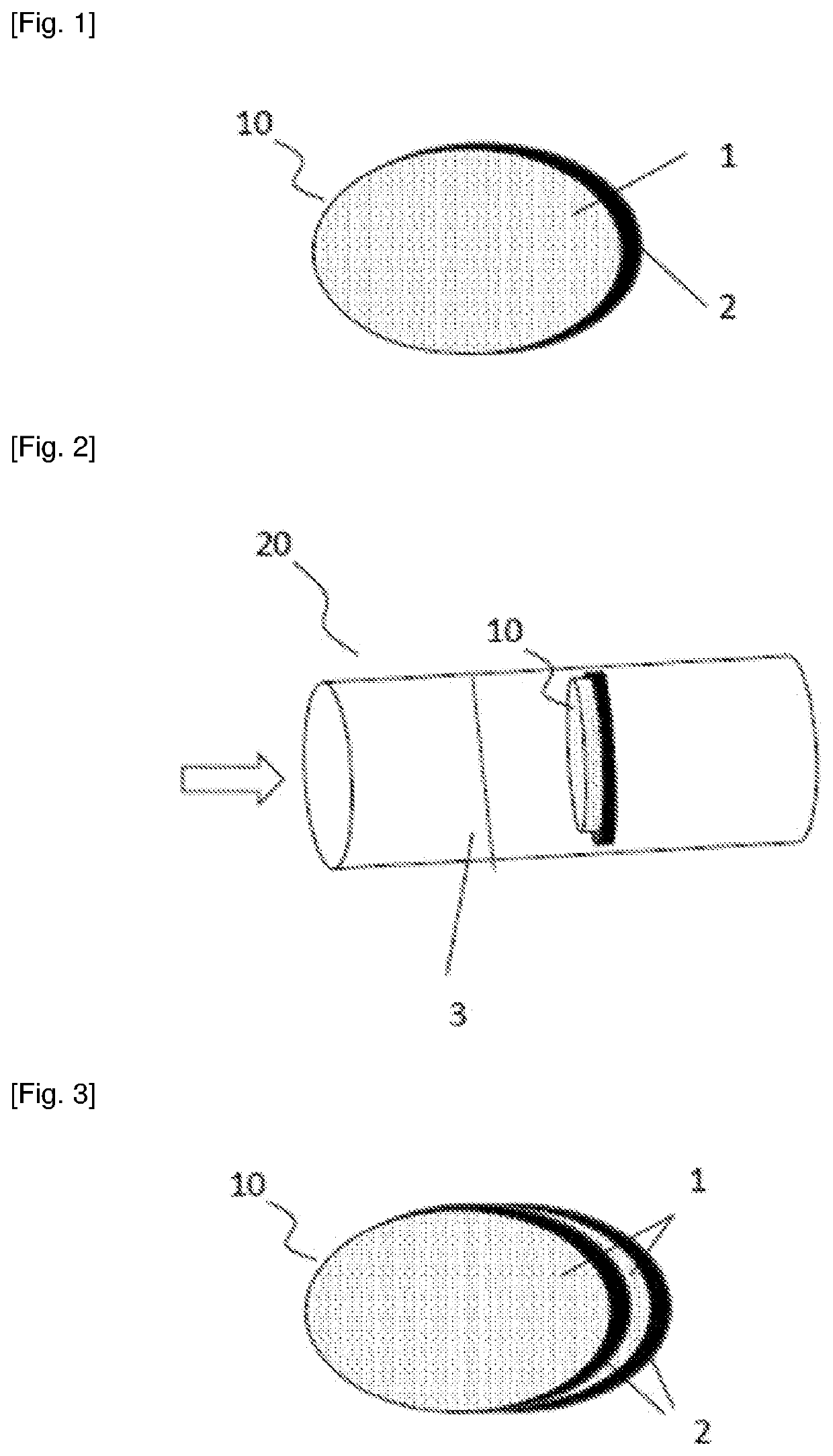
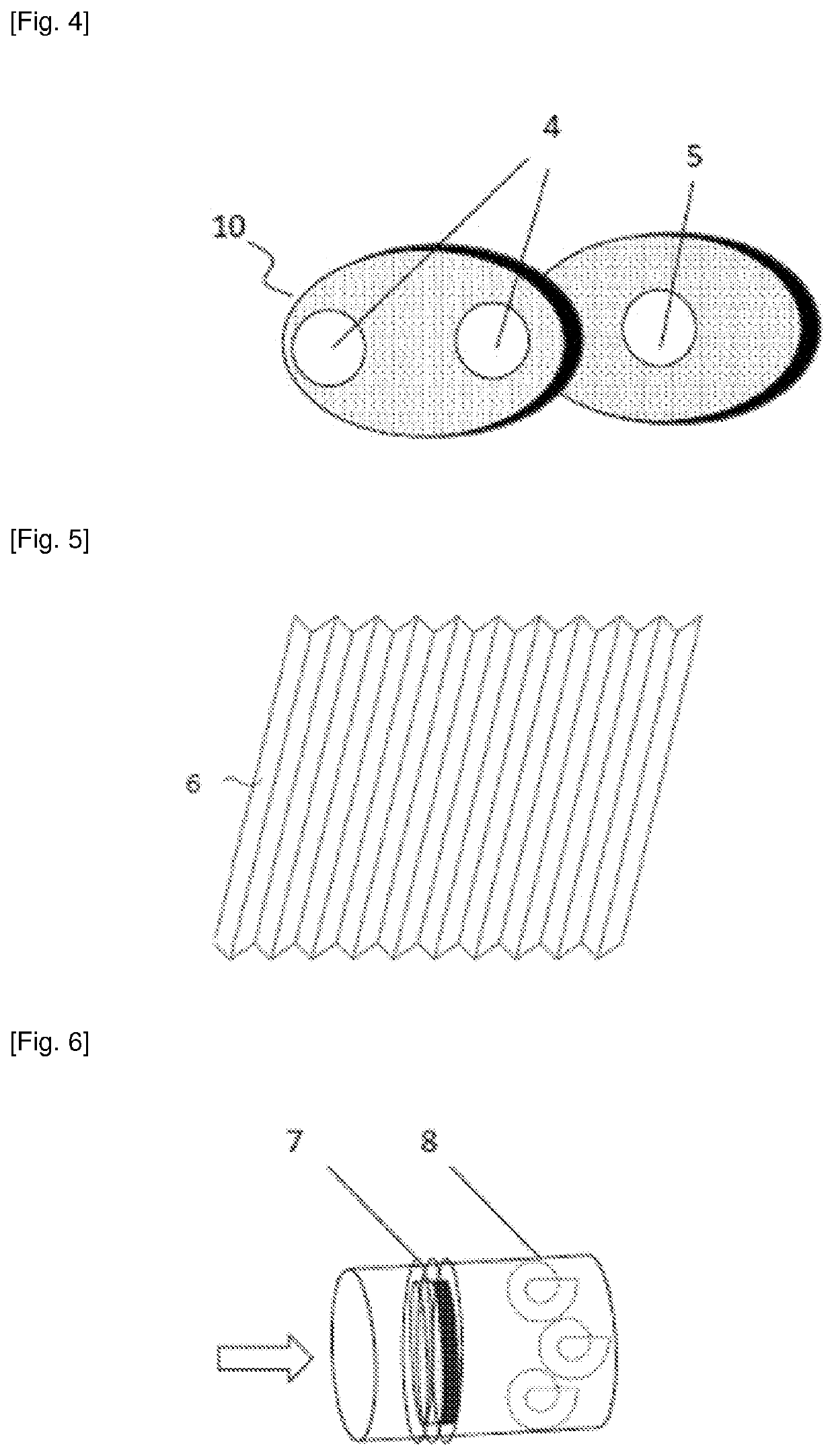
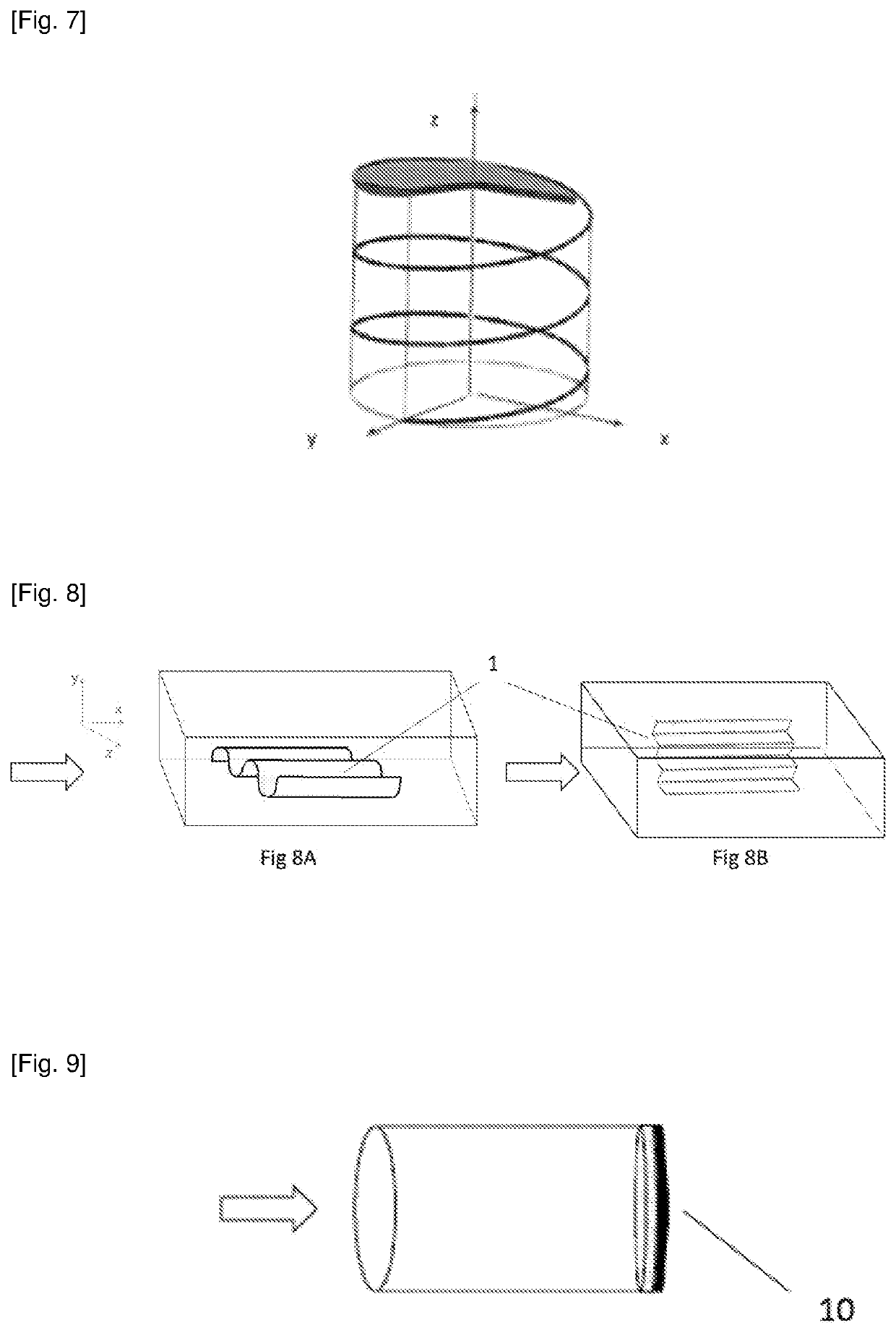
[0092]c. nr.6 wireless amagnetic heating modules composed by an embossed surface 1 (dot embossing) of about 6.3 micrometers of an amagnetic alloy as shown below;

[0093]d. a layer of adhesive resistant up to 300° C. and a dielectric plane 2 of 10 micrometers.

TABLE 3composition of the inductive amagnetic alloy, 1A experimentDiamagnetic metalsaluminium  98%Ferromagnetic metaliron 1.2%Other Metals0.8%

[0094]In number 6 wireless amagnetic heating modules are spaced from cylindrical dielectrics with a thickness of 2.5 mm and a diameter of 1 ...

experiment 2a

[0103]Embossed amagnetic top 1 composed of a 50 mm sheet for 50 mm and a thickness of 100 micrometers of an alloy so composed.

TABLE 4inductive amagnetic alloy 2A experimentMain Diamagnetic metalsCopperzinc64%35.25%Ferromagnetic metalsIronNickel0.1%  0.3%Other metals0.35% 

[0104]Results of the experimental tests 2A: Starting temperature: 26° C.; Temperature reached: 10° C.; Trial duration: 65 sec; Average power absorbed in the ascent: 65W.

experiment 2b

[0105]Embossed amagnetic top 1 composed of an inductive amagnetic foil of 50 millimeters by 50 millimeters and of a thickness of about 6 micrometres composed of

TABLE 5inductive amagnetic alloy 2B experimentDiamagnetic metalsAluminium 98%Ferromagnetic metalIron1.2%Other Metals0.8%

[0106]Results of the experimental tests 2B: Starting temperature: 34° C.; Temperature reached: 93° C.; Trial duration: 20 sec; Average power absorbed in the ascent: 60W.


PUM


Abstract

A non-magnetic wireless heating module is described. The module consists of a, preferably embossed, surface or plane and a dielectric surface or plane. The surface or plane is made of an inductive non-magnetic metal alloy that contains a first amagnetic metal or a first non-magnetic mixture of metals in a percentage between 85% and 99.99% by weight to the total weight and contains a second ferromagnetic or ferrimagnetic metal or a second ferromagnetic or ferrimagnetic mixture of metals in a percentage between 0.01% and 15% by weight to the total weight. The wireless amagnetic heating module is inserted into a chamber (for example a pipe or a portion of a pipe, a cubic container, a cistern . . . ) for the passage or storage of fluids, liquids, gases or solids; when the wireless amagnetic heating module is subjected to a variable electromagnetic field, it heats up, allowing heating, drying, passage of phase, . . . of the material in contact with it and contained in the chamber.

Description

TECHNICAL FIELD[0001]The present invention relates to a wireless induction heating module in amagnetic metal alloy.[0002]Induction heating modules of this type can be used to heat fluids or solids or gases in motion or stored in closed environments, where the wireless amagnetic heating module, object of the present invention, is placed or integrated within the storage or passage chamber for heating fluids, gases or solids in industrial processes.BACKGROUND ART[0003]Many industrial and domestic processes involve heating a fluid, a solid or a gas contained within a chamber of different sizes and shapes (for example a tube or a portion of a pipe, a cubic container, a cistern . . . ). Consider, for example, industrial drying processes or water heating in the civil sector.[0004]Conventionally, the material to be heated can be heated through external heating sources which insist on the walls of the chamber (for example a cistern, a pipe, . . . ) which, in turn, condense and irradiate the ...

Claims


Application Information

Patent Timeline
IPC IPC(8): H05B6/10H05B6/34
CPCH05B6/34H05B6/108
Inventor CORRADOCREMONESI, CHIARA
Owner E WENCO SRL
Learn More