Method and Apparatus for Alignment of a Line-Of-Sight Communications Link
- Summary
- Abstract
- Description
- Claims
- Application Information
AI Technical Summary
Benefits of technology
Problems solved by technology
Method used
Image

Examples
embodiment 1
for US Pat App Pub 2017 / 0033535—Top-Emitting Implant
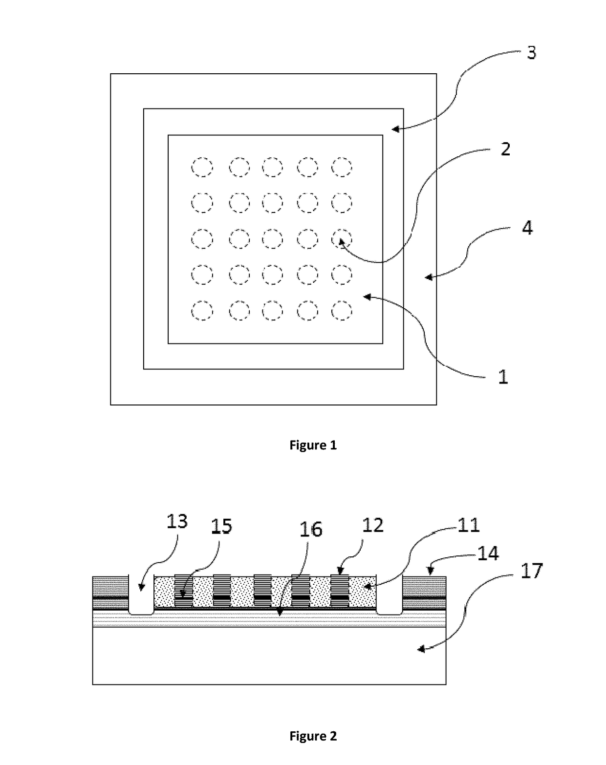
[0076]FIG. 1 shows an example of a first embodiment of the invention. In this example, a single solid structure is isolated from a surrounding ground with an etch, and where the single solid structure has within it ion implants. The ion implants create areas of the semiconductor material that are non-conductive, and these areas of non-conductivity force current flow through the lasing areas 2. Thus, the ion implants form a laser grid of multiple lasing areas 2 where current is confined to isolated regions in the structure where conductivity exists as compared to the nonconductive ion-implanted areas. The conductive and nonconductive areas form a grid of light which has a single metal contact on the single solid structure for the active positive (P) contact and a single negative (N) contact on the surrounding ground structure which is shorted to the N contact area at the bottom of the trench isolating the two areas or to negative me...
embodiment 2
for US Pat App Pub 2017 / 0033535—Bottom-Emitting Implant
[0117]FIG. 6 illustrates a cutaway view of an example of a second embodiment, where the second embodiment is a bottom-emitting device with implanted regions for current confinement. The GSG electrical waveguide can be seen solder bonded to the frame-ground structure and the active single laser mesa structure. FIG. 6 shows:[0118]601 Electrical Waveguide Substrate[0119]602 Ground Contact and Signal Contact in that order of GSG Electrical Waveguide[0120]603 Solder-Bonding GSG Waveguide to Laser Chip[0121]604 Plating Metal electrically connecting Signal pad of Electrical Waveguide to Lasers P contact[0122]605 P contact Metal[0123]606 Implanted Region that has been rendered non conductive[0124]607 P mirror[0125]608 Active region (quantum wells)[0126]609 N Mirror[0127]610 Conducting Layers in N Mirror where Implant has not reached[0128]611 Laser Beams Propagating through Laser Substrate[0129]612 Plating Metal shorted to N contact regi...
embodiments 1 and 2
Process for Embodiments 1 and 2 of US Pat App Pub 2017 / 0033535
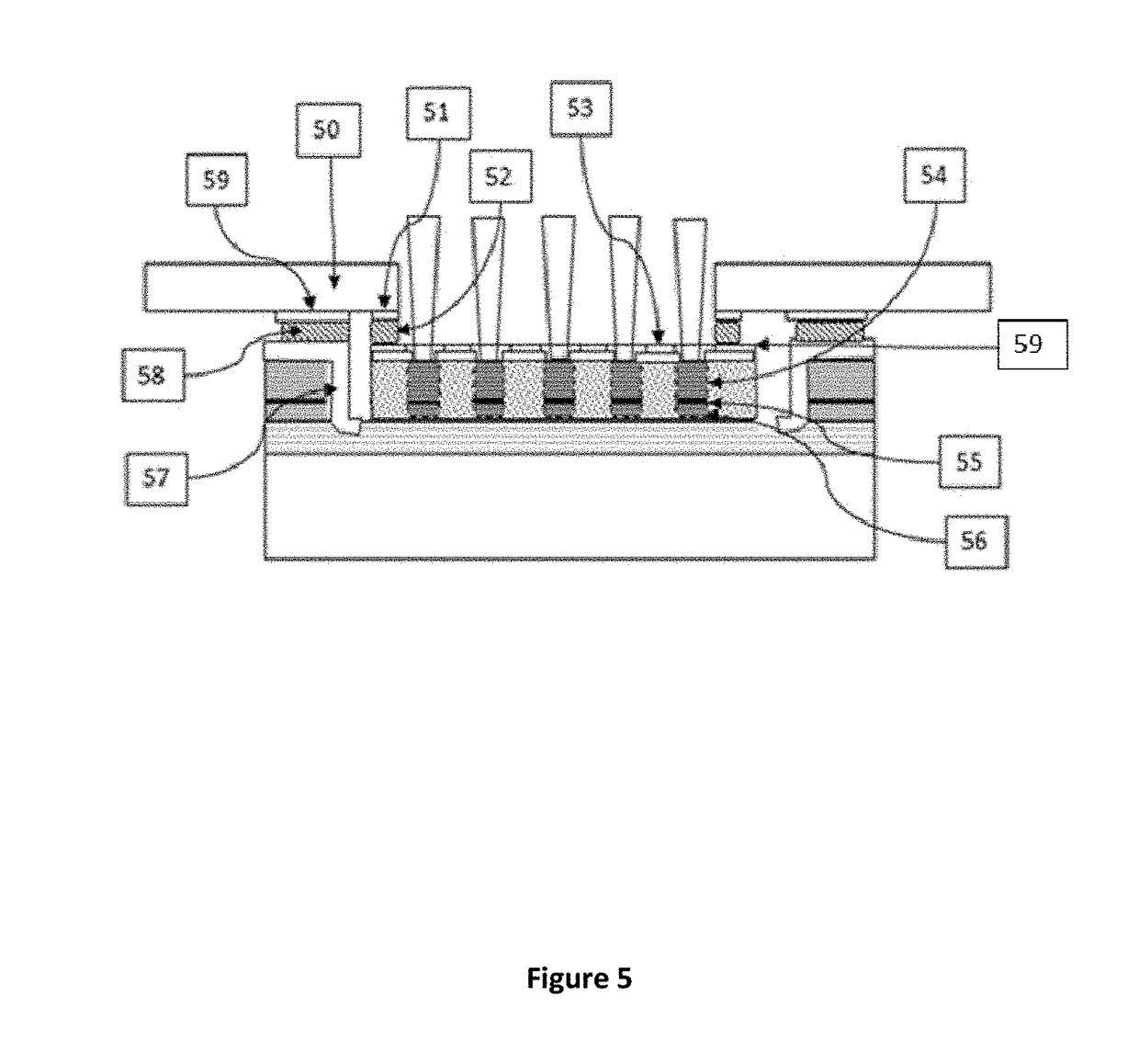
[0133]An example embodiment of the process steps to create the single structure for embodiments 1 and 2 with implant current confinement can be as follows.[0134]Step 1. Use photolithography to mask areas which will not have P Metal deposited.[0135]Step 2. Deposit P Metal (typically TiPtAu ˜2000 A)[0136]Step 3. Photolithography lift off and wafer cleaning. O2 descum or ash all organics off wafer.[0137]Step 4. Dielectric deposit (typically SiNx ˜[0138]Step 5. Photolithographic masking using either photoresist or metal deposited in areas to protect the epi material from being damaged from the implant which makes the unprotected regions non-conductive through ion bombardment. This step can be performed later in the process but may be more difficult due to more varied topology.[0139]Step 6. Implant—Those skilled in the art of calculating the implant doses will determine the dose and species of implant needed to disrupt the mat...
PUM
 Abstract
Description
Claims
Application Information
 - Generate Ideas
- Intellectual Property
- Life Sciences
- Materials
- Tech Scout
- Unparalleled Data Quality
- Higher Quality Content
- 60% Fewer Hallucinations
Browse by: Latest US Patents, China's latest patents, Technical Efficacy Thesaurus, Application Domain, Technology Topic, Popular Technical Reports.
© 2025 PatSnap. All rights reserved.Legal|Privacy policy|Modern Slavery Act Transparency Statement|Sitemap|About US| Contact US: help@patsnap.com