
Methods of applying self-forming artificial solid electrolyte interface (SEI) layer to stabilize cycle stability of electrodes in lithium batteries

Active Publication Date: 2019-02-28
GM GLOBAL TECH OPERATIONS LLC
View PDF4 Cites 12 Cited by
  • Summary
  • Abstract
  • Description
  • Claims
  • Application Information

AI Technical Summary

Benefits of technology

The patent is about methods for making a negative electrode for a battery using a special coating called a fluoropolymer. This coating helps improve the stability of the battery and maintain its capacity. The negative electrode can be made using metallic lithium, which has the highest theoretical capacity and the lowest potential for reacting with other materials in the battery. However, lithium metal batteries can also have some potential drawbacks, such as being unreliable or failing prematurely. These methods and techniques described in the patent offer a way to improve the performance and lifespan of lithium metal batteries.

Problems solved by technology

However, current anode materials comprising silicon (e.g., silicon metal or silicon alloys) can suffer from large volumetric expansion.
Large volume changes (e.g., volume expansion / contraction of greater than 300%) of silicon-containing materials during lithium insertion / extraction (e.g., intercalation / alloy and deintercalation / dealloy-intercalation / alloy) can result in physical damage to the electrode, including wrinkling, fracture, or cracking.
Such volumetric expansion thus can lead to loss of electrical contact and electrode activity.
The large volumetric expansion during intercalation / alloying of the anode comprising silicon, or other large volume expansion materials, can thus result in a decline of electrochemical cyclic performance, diminished Coulombic charge capacity (capacity fade), and extremely limited, poor cycle life.
However, lithium metal batteries also have potential downsides, including possibly exhibiting unreliable or diminished performance and potential premature electrochemical cell failure.
There are two primary causes for performance degradation with lithium negative electrodes.
Side reactions can occur between the lithium metal and species in the adjacent electrolyte disposed between the positive and negative electrodes, which can compromise coulombic efficiency and cycling lifetime of rechargeable lithium batteries.
The metal dendrites may form sharp protrusions that potentially puncture the separator and cause an internal short circuit, which may cause cell self-discharge or cell failure through thermal runaway.

Method used


Image

  • Methods of applying self-forming artificial solid electrolyte interface (SEI) layer to stabilize cycle stability of electrodes in lithium batteries
  • Methods of applying self-forming artificial solid electrolyte interface (SEI) layer to stabilize cycle stability of electrodes in lithium batteries
  • Methods of applying self-forming artificial solid electrolyte interface (SEI) layer to stabilize cycle stability of electrodes in lithium batteries

Examples


example 1

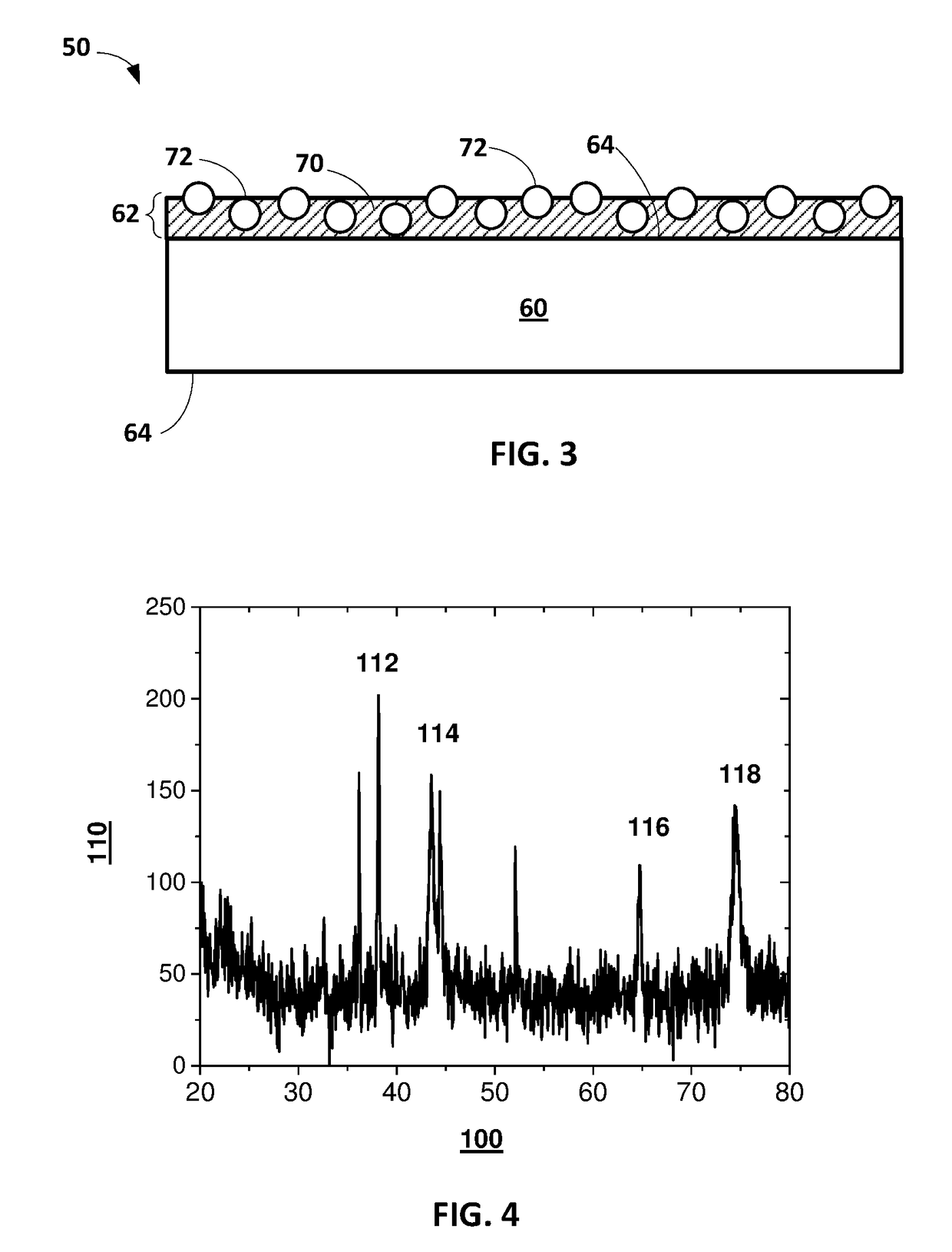
[0088]A radio frequency magnetron sputtering system is used to deposit polytetrafluoroethylene (PTFE) coating at room temperature (about 21° C.). A 3 inch diameter PTFE disk is used as a sputtering target. When the target is bombarded with Ar ions, the sputtered PTFE is then deposited on a lithium metal disk / substrate. The RF power is 170 W, with 2 sccm Ar flow. The coating thickness is around 1 micron.

example 2

[0089]An electrochemical test is conducted as follows. A symmetric cell with PTFE coated Li disk (13 mm in diameter) as a negative electrode is assembled in Ar filled glovebox. The electrolyte in the cell includes 1M LiPF6 in EC:DEC. The cell is cycled with current density of 1 mA / cm2 and a capacity of 4 mAh / cm2. The cut-off voltage is ±0.5 voltage. The control cell is uncoated Li disks with the same size.

[0090]FIG. 6 shows cycle performance in a plot of voltage (V) on an y-axis 142 over time (hours) on an x-axis 140 for a symmetric cell with the PTFE coated Li disk 150 prepared in accordance with certain aspects of the present disclosure and the control 152 incorporating an uncoated Li disk. As can be seen, the control cell 152 fails around 125 hours, while the PTFE coated Li disk 150 continues successfully cycling past 450 hours. Thus, the presence of the composite surface layer on the lithium disk improves the cycle stability when it serves as a lithium metal electrode in a symme...

example 3

[0091]A half cell with PTFE coated Si thin film (100 nm thick and 12 mm in diameter) on a Cu substrate is assembled in Ar filled glovebox, with a 15 mm Li disk as the counter electrode. In this example, the silicon is not prelithiated, as it is incorporated into a half cell where the counter Li electrode provides sufficient Li to the system. The electrolyte in the cell includes 1M LiPF6 in EC:DEC. The cell is cycled with current density of 10 micron A / cm2 and the cut-off voltage is 1V and 0.05V. The control cell is uncoated Si film electrode with the same size.

[0092]FIG. 7 shows comparative cycle performance in both a plot of charge capacity (Ah) on an y-axis 162 versus an x-axis 160 of cycle index for a symmetric cell with the PTFE coated silicon thin film 170 prepared in accordance with certain aspects of the present disclosure and a control 172 incorporating an uncoated silicon film copper disk. FIG. 7 also shows Coulombic Efficiency (CE) on the opposite y-axis 164 versus cycle i...


PUM


Abstract

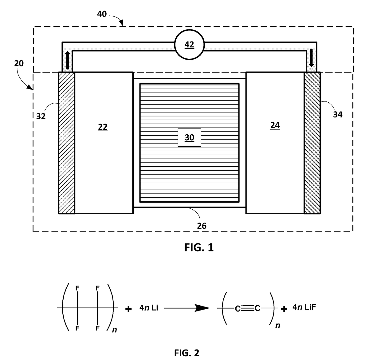
A method of making a negative electrode for an electrochemical cell includes applying a fluoropolymer via a deposition process to one or more surface regions of an electroactive material. The electroactive material may be selected from the group consisting of: lithium metal, silicon metal, silicon-containing alloys, and combinations thereof. The fluoropolymer reacts with lithium to form a composite surface layer on the one or more surface regions that comprises an organic matrix material having lithium fluoride particles distributed therein. Electrochemical cells including such negative electrode are also provided.

Description

GOVERNMENT SUPPORT[0001]This invention was made with government support under DE-EE0007787 awarded by the U.S. Department of Energy. The Government has certain rights in the invention.INTRODUCTION[0002]This section provides background information related to the present disclosure which is not necessarily prior art.[0003]The present disclosure relates to methods of making a negative electrode for an electrochemical cell including applying a fluoropolymer to an electroactive material comprising lithium or silicon that self-forms a composite layer serving as an artificial solid electrolyte interface (SEI) layer to enhance cycle stability of electrodes and maintain charge capacity of the electrochemical cell. The present disclosure also relates to negative electrodes made from such processes.[0004]By way of background, high-energy density, electrochemical cells, such as lithium-ion batteries can be used in a variety of consumer products and vehicles, such as Hybrid Electric Vehicles (HE...

Claims


Application Information

Patent Timeline
IPC IPC(8): H01M4/04H01M4/60H01M4/38H01M10/0525
CPCH01M4/0421H01M4/602H01M2004/027H01M4/386H01M10/0525H01M4/382H01M4/1395H01M4/366H01M4/628H01M4/0445H01M4/134H01M4/62H01M10/058Y02E60/10
Inventor XIAO, XINGCHENG
Owner GM GLOBAL TECH OPERATIONS LLC
Learn More