
Temperature control system for microfluidic device

a technology of microfluidic devices and control systems, which is applied in fluid controllers, laboratory glassware, instruments, etc., can solve the problems of limiting the temperature gradient that droplets experience, the complexity of design and control methods, and the linearity of spatial temperature gradients, so as to reduce the lateral flow of heat within the device, reduce the lateral flow of heat, and control the temperature profile. the effect of high degree of freedom

Pending Publication Date: 2018-08-09
SHARP LIFE SCI EU LTD
View PDF4 Cites 5 Cited by
  • Summary
  • Abstract
  • Description
  • Claims
  • Application Information

AI Technical Summary

Benefits of technology

The invention provides a reader for a microfluidic device that has a temperature control element. This allows for precise temperature control in the microfluidic device. The reader can be easily attached to the microfluidic device and has contact elements that make contact with the first substrate of the device, allowing for heat transfer. The first substrate is preferably made of a low thermal conductivity material, such as glass or plastics, to further enhance the temperature control. The use of a single temperature control element reduces complexity and the need for a complex temperature control system.

Problems solved by technology

This approach however suffers from the disadvantage that the rates of temperature change that can be achieved are generally low thereby limiting the temperature gradient that the droplets experience.
However, each of the aforementioned approaches and methods have disadvantages for this and many other chemical and biochemical operations and assays.
Such disadvantages include: the complexity of the design and the control methods; the non-linearity of the spatial temperature gradient; the large physical size of the apparatus; and the resulting high manufacturing cost.
The performance and scope of operation of such devices is therefore limited.

Method used


Image

  • Temperature control system for microfluidic device
  • Temperature control system for microfluidic device
  • Temperature control system for microfluidic device

Examples


embodiment 1

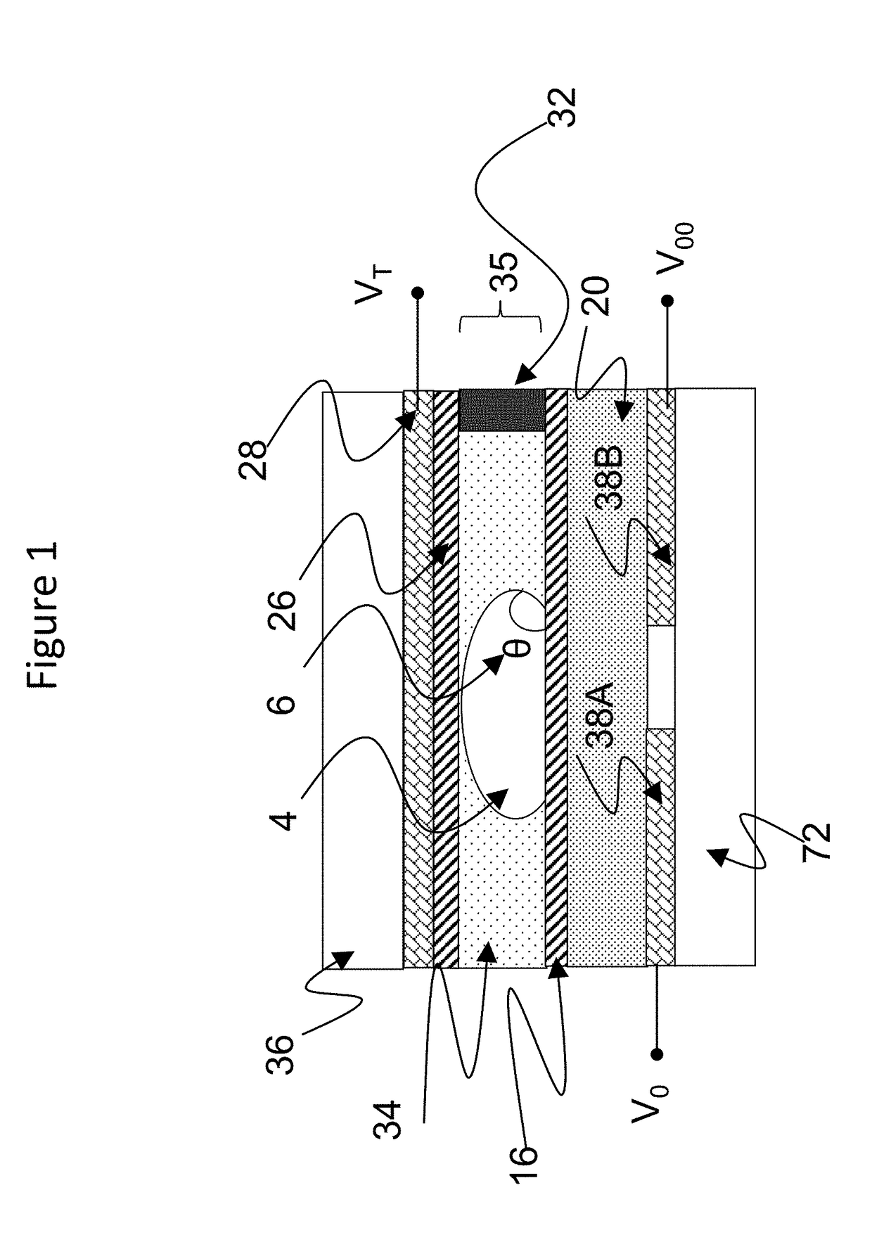
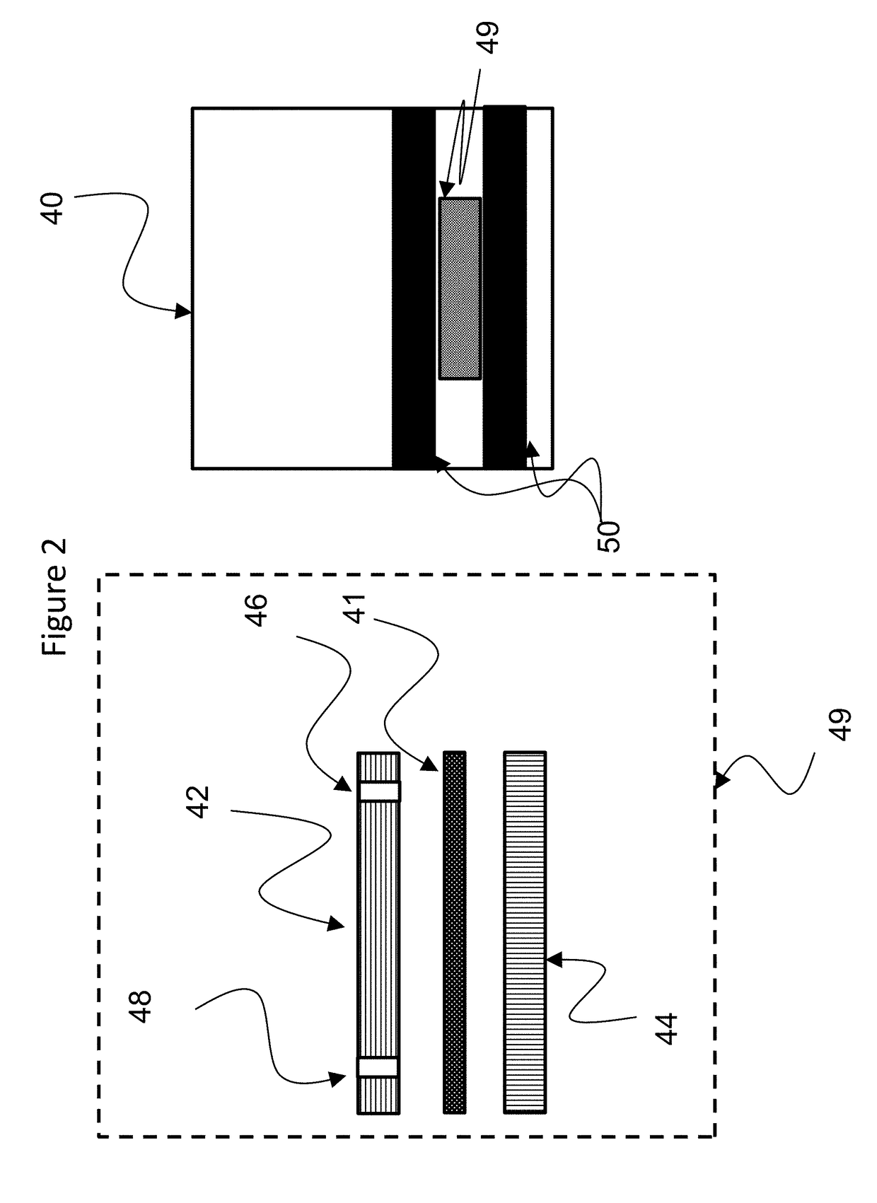
[0098]FIG. 2 shows an exemplary droplet microfluidic handling system according to a first embodiment of the present invention. The system is in two parts comprising a cartridge 49 and a reader 40.

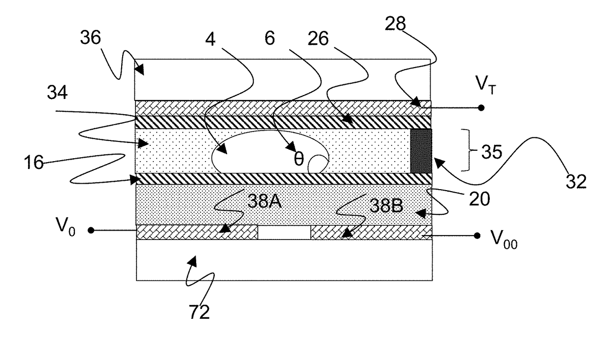
[0099]The cartridge 49 is shown comprised of the EWOD device 41, which may optionally be mounted into a housing, e.g. a plastic housing to form a microfluidic cartridge 49. The housing may, for example, be comprised of upper 42 and lower 44 plastic parts, though this is a matter of design and many arrangements are possible. Typically the cartridge 49 includes input structures 46 (e.g. holes) for entry of fluids and may optionally also include output structures 48 whereby liquid may be ejected from the device. The input and output structures are connected fluidically to the fluid gap 35 (not shown in FIG. 2) of the EWOD device whereby fluid may be input to and / or extracted from the EWOD device. The EWOD device typically contains a dispensing structure for generating liquid droplets 4 in the ...


PUM


Abstract

A heating system for a EWOD device using a single, spatially-structured temperature control element, used to create a zone on the device with a specific temperature profile. The heating system uses multiple contact regions between the temperature control element and the device. One or more of the contact regions are separated from the temperature control element by one or more thermally resistive layers whose purpose is to restrict heat flow from the temperature control element to the device, and further to restrict lateral flow of heat between adjacent contact regions. The heating system can use one or more materials with different thermal resistance to alter the heat flow to different regions of the device. The spatial location of the contact regions is also used to determine the temperature profile within the device. The device has an optional temperature control element which offsets the low temperature point from the inlet temperature. This invention also describes methods to process multiple droplets within the multiple temperature zones.

Description

RELATED APPLICATION DATA[0001]Pursuant to 35 U.S.C. § 119, this application claims priority benefit to European Patent Application No. 17154839.9 filed on Feb. 6, 2017, the content of which is incorporated here by reference.TECHNICAL FIELD[0002]The present invention relates to a structure for creating a temperature profile within a microfluidic device. More specifically, the present invention relates to a heating and / or cooling system for an active matrix electro wetting on dielectric (AM-EWOD) digital microfluidic device which provides a temperature profile via a single temperature control element. The invention also relates to methods of using the temperature profile to control the temperature of fluids in the device.BACKGROUND ART[0003]Electro-wetting on dielectric (EWOD) is a well-known technique for manipulating droplets of fluid by application of an electric field. Active Matrix EWOD (AM-EWOD) refers to implementation of EWOD in an active matrix array incorporating transistors...

Claims


Application Information

Patent Timeline
Patent Type & Authority Applications(United States)
IPC IPC(8): B01L3/00G01N27/447B01L7/00
CPCB01L3/50273G01N27/44791B01L7/00B01L3/502715B01L2300/1805B01L2400/0427B01L3/5027B01L3/502784B01L7/54B01L2300/1827B01L2300/1861B01L2300/1822B01L2300/1894B01L7/525B01L2300/1883F28F2013/005B01L2300/0663
Inventor ROBERTS, PHILLIP MARK SHRYANE
Owner SHARP LIFE SCI EU LTD
Learn More