
Aqueous pyridinium cation-based redox flow batteries

a technology of redox flow batteries and pyridinium cation, which is applied in the direction of aqueous electrolyte fuel cells, cell components, electrochemical generators, etc., can solve the problems of aqueous flow battery designs with functional or cost-performance limitations, impede the large-scale adoption of this technology, and cannot be directly connected to the grid

Active Publication Date: 2018-07-05
UCHICAGO ARGONNE LLC
View PDF1 Cites 2 Cited by
  • Summary
  • Abstract
  • Description
  • Claims
  • Application Information

AI Technical Summary

Benefits of technology

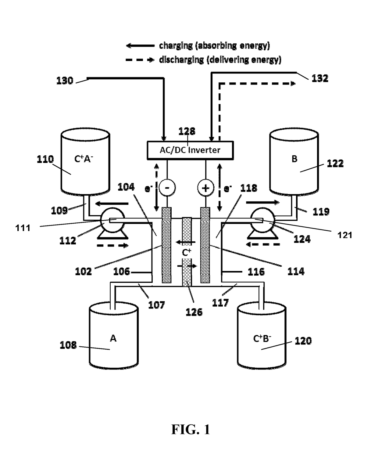
The present invention provides an aqueous redox flow battery that uses a negative electrode and a positive electrode to balance charges during charging and discharging. The electrodes circulate the electrolytes over them while cations shuttle between the electrodes to maintain the electrodes in a balanced state. The battery uses a pyridinium compound as the redox reactant in the negative electrode and a combination of different salts in the positive electrode. The redox flow battery has a high energy density and can be used for energy storage and conversion.

Problems solved by technology

While alternative energy technologies exist, they cannot be directly connected to the grid because of their variable output.
All current aqueous flow battery designs have functional or cost-performance limitations that hamper large scale adoption of this technology.

Method used


Image

  • Aqueous pyridinium cation-based redox flow batteries
  • Aqueous pyridinium cation-based redox flow batteries
  • Aqueous pyridinium cation-based redox flow batteries

Examples


example 1

Preparation of Pyridinium Redox Reactants.

[0040]N,N′-(ethan-1,2-diyl)-2,2′-bipyridinedium dibromide (A) can be prepared by reaction of 2,2′-bipyridine with ethylene dibromide (1,2-dibromoethane) in 95% yield, as illustrated below.

[0041]A solution of 2,2′-bipyridyl (4.7 g, 30 mmol) in 1,2-dibromoethane (30 mL) was refluxed for 12 h, during which a precipitate was accumulated. The reaction was cooled to room temperature. The solid was filtered off and washed with acetone, hexanes, and then dried under vacuum to afford A (6.5 g, 95%) as a yellow solid. 1H NMR (300 MHz, D2O) δ 9.14 (d, J=5.8 Hz, 2H), 8.91 (d, J=8.2 Hz, 2H), 8.82 (t, J=8.0 Hz, 2H), 8.29 (dd, J =9.1, 4.5 Hz, 2H), 5.29 (s, 4H).; 13C NMR (75 MHz, D2O) δ 148.3, 147.1, 139.7, 130.7, 128.5, 52.4.

[0042]Bipyridinium compounds N,N′-(ethan-1,2-diyl)-4,4′-dimethyl-2,2′-bipyridinedium dibromide (B), and N,N′-(ethan-1,2-diyl)-5,5′-dimethyl-2,2′-bipyridinedium dibromide (C) were prepared from the corresponding methyl-substituted bipyr...

example 2

Electrochemical Evaluation of Pyridinium Redox Reactants.

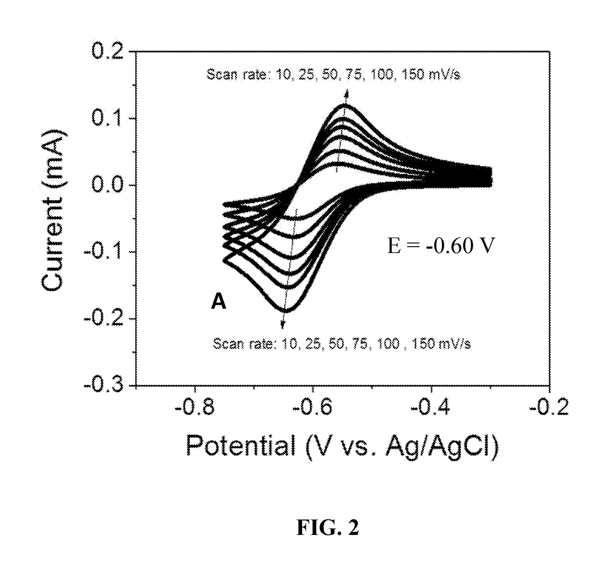
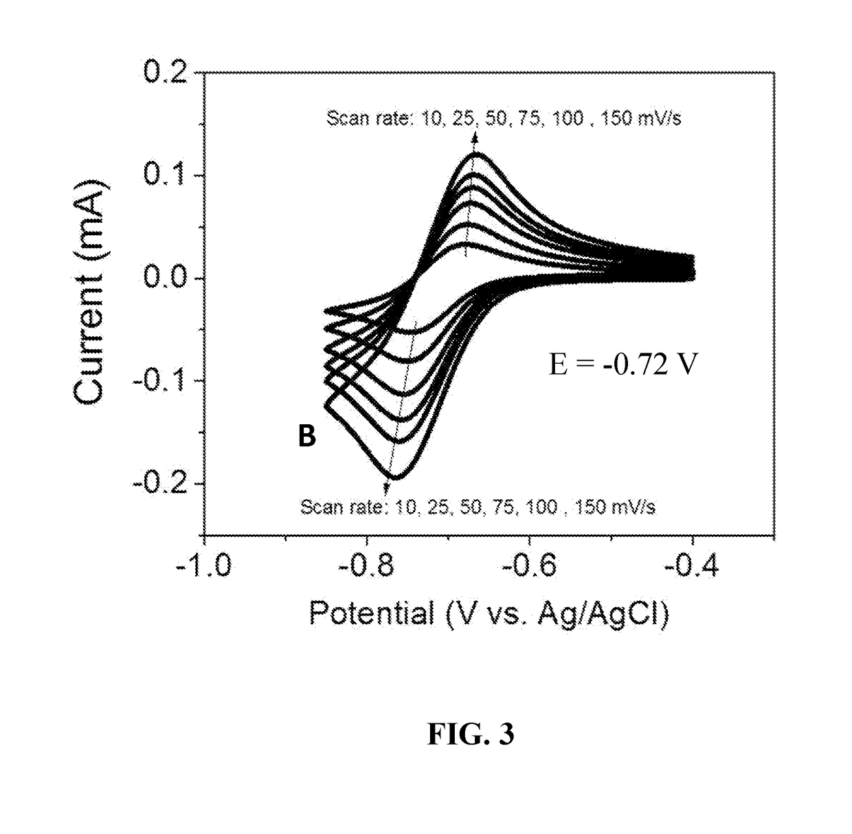
[0043]The electrochemical properties of bipyridinium compounds (A), (B), and (C) were evaluated using cyclic voltammetry in a GC|Pt|Ag / AgCl three-electrode cell containing a 10 mM concentration of the redox reactant compound in 0.5 M aqueous NaCl as the supporting electrolyte. Compounds (A), (B), and (C) exhibited well-defined, reversible redox waves with redox potentials of −0.60 V, −0.72V and −0.72 V, respectively, versus Ag / AgCl (see FIGS. 2, 3, and 4). These materials had surprisingly good properties for use as anolyte redox materials, including reduction potentials that are about 70 mV lower than that of viologen (a commonly used anolyte reactant in flow batteries), good solubility in water (typically greater than 2 M), and good electrochemical stability. In addition, compounds such as (A), (B), and (C) can be readily synthesized in just one step from commercially available starting materials in high yields (up to 100% at...


PUM

PropertyMeasurementUnit
reduction potentialsaaaaaaaaaa
cell voltageaaaaaaaaaa

Abstract

The present invention provides an aqueous redox flow battery comprising a negative electrode immersed in an aqueous liquid negative electrolyte, a positive electrode immersed in an aqueous liquid positive electrolyte, and a cation-permeable separator (e.g., a porous membrane, film, sheet, or panel) between the negative electrolyte from the positive electrolyte. During charging and discharging, the electrolytes are circulated over their respective electrodes. The electrolytes each comprise an electrolyte salt (e.g., a lithium or sodium salt), a redox reactant. The negative redox reactant comprises a pyridinium compound of Formula (I) as described in the specification

Description

CONTRACTUAL ORIGIN OF THE INVENTION[0001]The United States Government has rights in this invention pursuant to Contract No. DE-AC02-06CH11357 between the United States Government and UChicago Argonne, LLC representing Argonne National Laboratory.FIELD OF THE INVENTION[0002]This invention relates to redox flow batteries. More particularly, this invention relates to aqueous redox flow batteries utilizing pyridinium cation-based redox materials.BACKGROUND OF THE INVENTION[0003]Low-cost, scalable energy storage systems are needed to improve the energy efficiency of the electrical grid (e.g., load-leveling, frequency regulation) and to facilitate the large-scale penetration of renewable energy resources (e.g., wind, solar). While alternative energy technologies exist, they cannot be directly connected to the grid because of their variable output. Electrochemical energy storage may provide the best combination of efficiency, cost, and flexibility to enable these applications. Of particula...

Claims


Application Information

Patent Timeline
Patent Type & Authority Applications(United States)
IPC IPC(8): H01M8/08H01M8/18H01M8/023H01M8/04082
CPCH01M8/08H01M8/188H01M2300/0002H01M8/04201H01M8/023H01M4/90H01M8/04186Y02E60/50
Inventor ZHANG, ZHENGCHENGHUANG, JINHUAGALLAGHER, KEVIN
Owner UCHICAGO ARGONNE LLC
Learn More