
Sensor device with a soft magnetic alloy having reduced coercivity, and method for making same

a soft magnetic alloy and coercivity reduction technology, applied in the field of magnetic sensors, can solve problems such as inaccuracy of magnetic field strength measurements, and achieve the effects of reducing coercivity, reducing coercivity, and reducing coercivity

Active Publication Date: 2018-02-01
MELEXIS TECH NV
View PDF3 Cites 5 Cited by
  • Summary
  • Abstract
  • Description
  • Claims
  • Application Information

AI Technical Summary

Benefits of technology

The patent describes a method for reducing mechanical stress on semiconductor material and magnetic alloy, which can improve the performance of magnetic sensors. The method involves using a first elastomeric material or compound between the semiconductor material and magnetic alloy. Another advantage is the use of at least one permanent magnet to create a magnetic field, as opposed to using coils and switched currents, which can require high currents and have long annealing times and associated equipment and energy costs.

Problems solved by technology

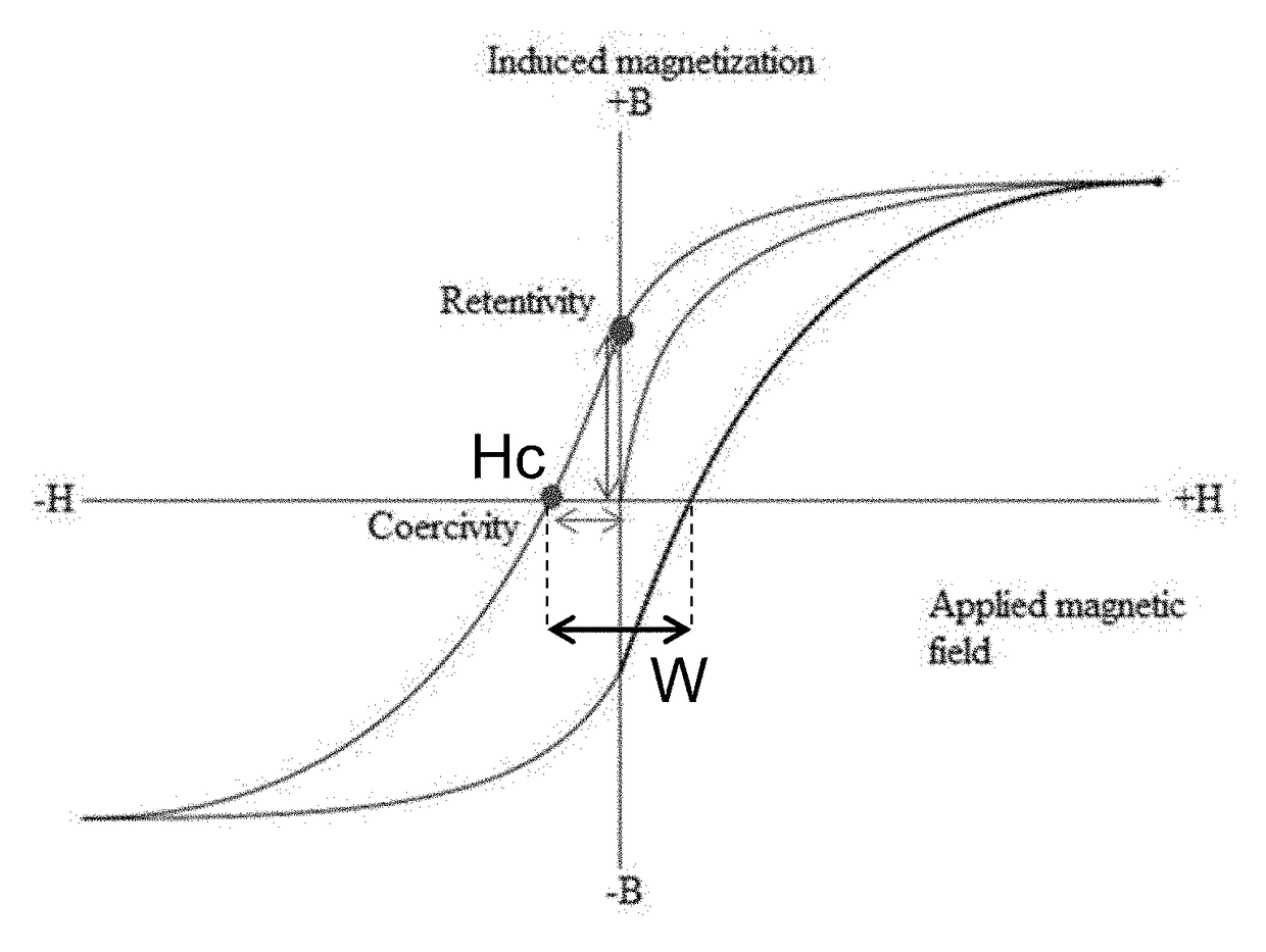
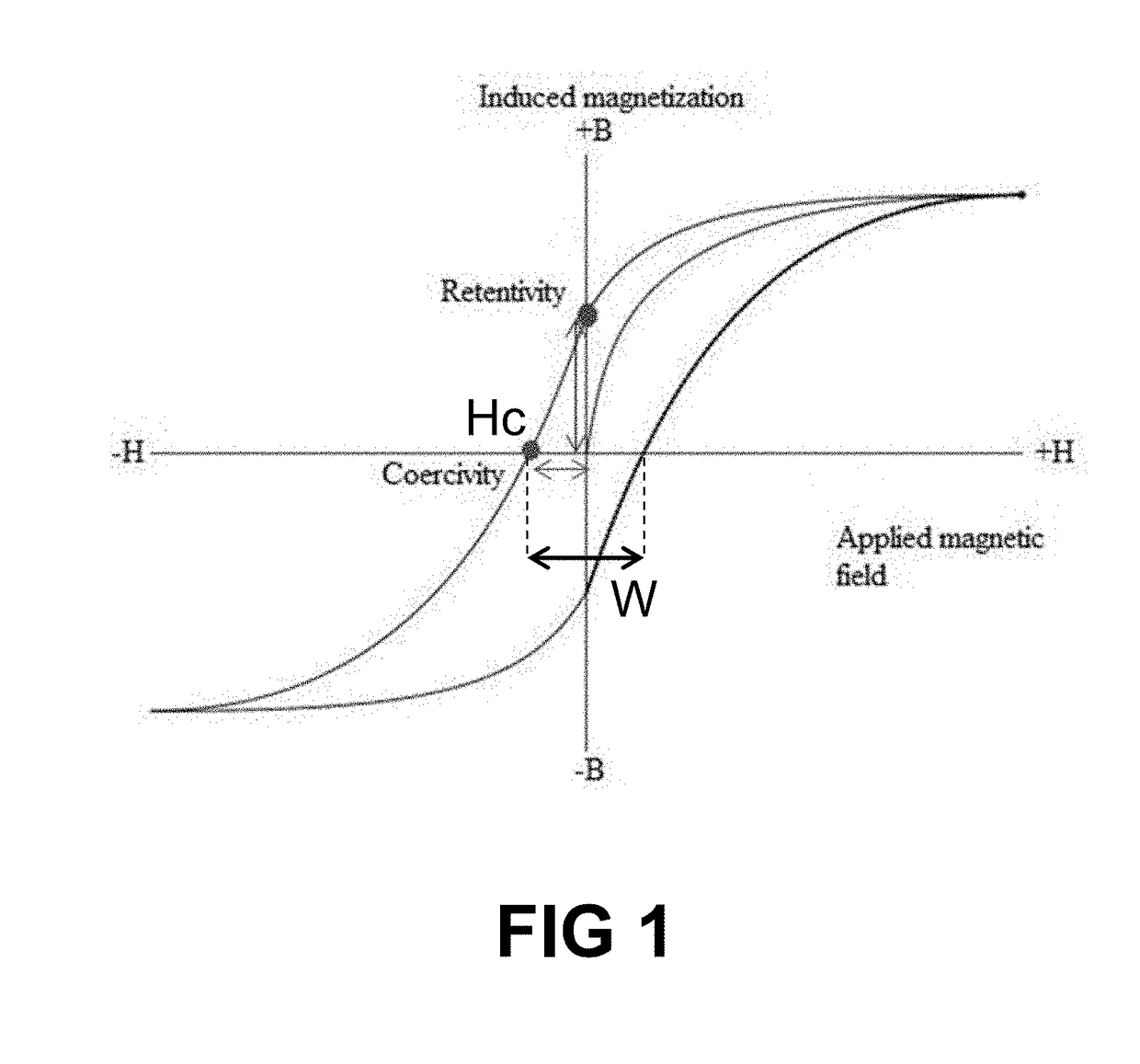
A problem of magnetic material is that it has a hysteresis (related to magnetic coercivity) which causes inaccuracies of magnetic field strength measurements.

Method used


Image

  • Sensor device with a soft magnetic alloy having reduced coercivity, and method for making same
  • Sensor device with a soft magnetic alloy having reduced coercivity, and method for making same
  • Sensor device with a soft magnetic alloy having reduced coercivity, and method for making same

Examples


Embodiment Construction

[0069]The present invention will be described with respect to particular embodiments and with reference to certain drawings but the invention is not limited thereto but only by the claims. The drawings described are only schematic and are non-limiting. In the drawings, the size of some of the elements may be exaggerated and not drawn on scale for illustrative purposes. The dimensions and the relative dimensions do not correspond to actual reductions to practice of the invention.

[0070]Furthermore, the terms first, second and the like in the description and in the claims, are used for distinguishing between similar elements and not necessarily for describing a sequence, either temporally, spatially, in ranking or in any other manner. It is to be understood that the terms so used are interchangeable under appropriate circumstances and that the embodiments of the invention described herein are capable of operation in other sequences than described or illustrated herein.

[0071]Moreover, t...


PUM


Abstract

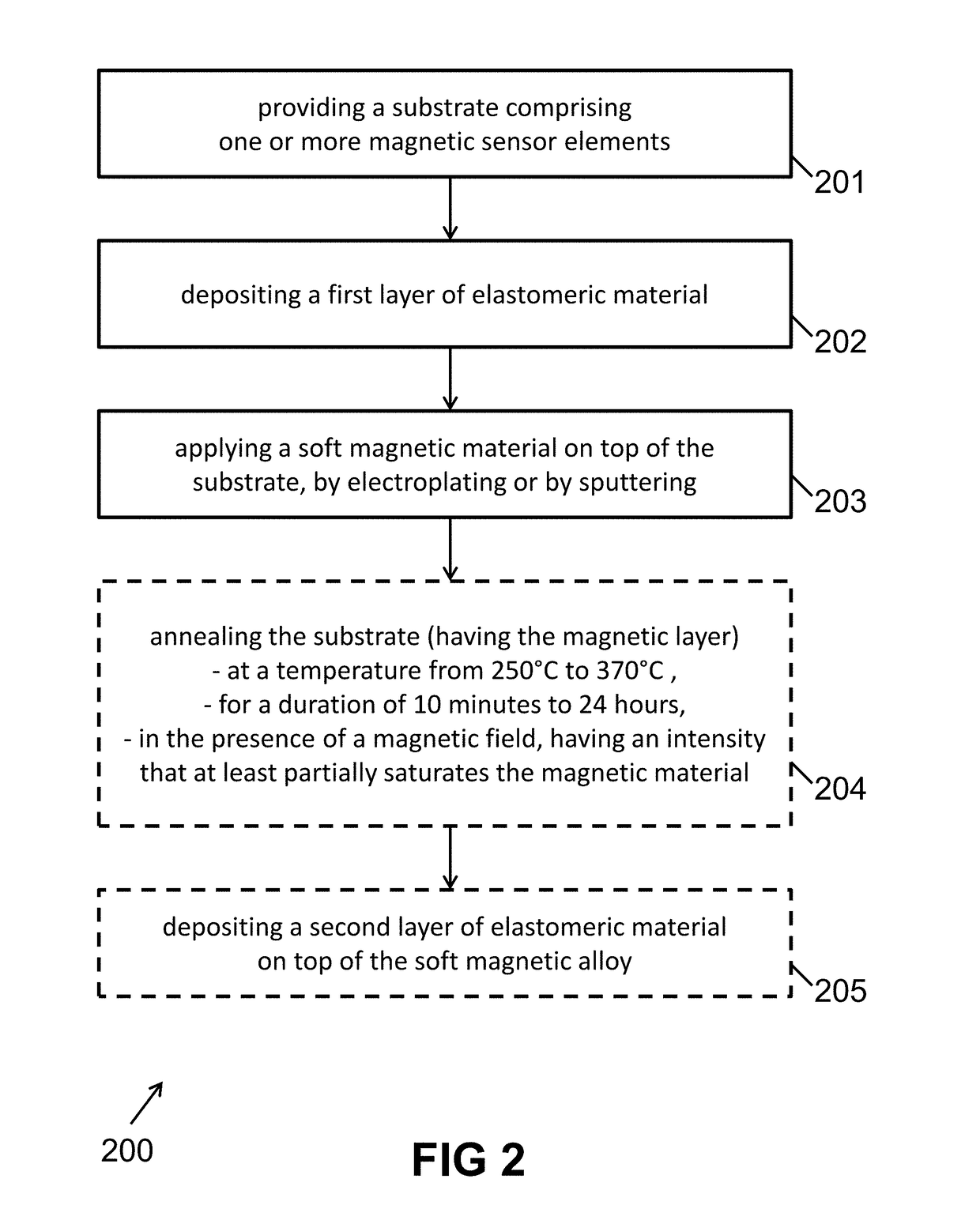
A sensor device comprising a substrate, the substrate comprising one or more magnetic sensor elements; a first elastomeric material on top of the one or more magnetic sensor elements; a magnetic layer comprising a soft magnetic metal alloy deposited by electroplating or by sputtering on top of the first elastomeric material; and optionally a second elastomeric material on top of the magnetic layer. The substrate may be a CMOS device with IMC encapsulated between two polyimide layers. The magnetic material may be annealed at 250° C. to 295° C. using a constant or rotating magnetic field having a strength in the range from 100 to 300 mTesla. The soft magnetic alloy is arranged as Integrated Magnetic Concentrator (IMC).

Description

FIELD OF THE INVENTION[0001]The present invention relates to the field of magnetic sensors and methods for making such magnetic sensors. More particularly, the present invention relates to a magnetic sensor having a reduced hysteresis, and methods for making such sensors.BACKGROUND OF THE INVENTION[0002]Magnetic sensors can be used in a wide field of applications. One exemplary application of magnetic sensors is as an angle sensor for controlling a motor. Magnetic sensors can be used for determining a quantity and / or a direction of a magnetic field.[0003]Several magnetic sensor designs have been developed. One interesting design of a magnetic sensor is based on a semiconductor substrate comprising magnetically sensitive regions obtained by embedding magnetic sensing elements in the semiconductor substrate in the form of so called “Horizontal Hall elements”, and by arranging a magnetic substance on top of the semiconductor substrate for bending the magnetic flux from a horizontal dir...

Claims


Application Information

Patent Timeline
IPC IPC(8): G01R33/07H01F41/14H01F10/32H01L43/06G01R33/09G01R33/02
CPCG01R33/072G01R33/091H01F41/14H01F10/32H01L43/06G01R33/02G01R33/07H10B61/00H10N59/00H10N52/00H10N52/01G01R33/0011G01R33/0052
Inventor BURSSENS, JAN-WILLEMRACZ, ROBERT
Owner MELEXIS TECH NV
Learn More