
High manganese steel pipe with step-out weld zone erosion-corrosion resistance and method of making the same

Active Publication Date: 2017-11-02
POSCO
View PDF10 Cites 6 Cited by
  • Summary
  • Abstract
  • Description
  • Claims
  • Application Information

AI Technical Summary

Benefits of technology

The present patent provides a novel weld metal and methods of making and using it to produce high manganese steel slurry pipes through seam welding. The weld metal has been designed to have adequate strength, toughness, and high erosion / corrosion resistance. The welding process uses submerged arc welding and the method includes supplying the high manganese steel, metal cored wire, and controlling the weld metal chemistry and heat input to prevent cracking and maintain strength in the weld and heat-affected zones. The metal cored wire contains carbon, silicon, manganese, sulfur, phosphorous, and iron. The technical effect of this patent is to provide a more robust and durable welded structure for high manganese steel slurry pipes.

Problems solved by technology

These pipelines undergo severe erosion-corrosion damages during service with the lowest portion / point of the pipeline (6 o'clock positon) experience the most severe erosion-corrosion wear.
However, most engineering materials considered so far have found only niche applications due to either relatively poor wear / erosion performance (e.g., polymer liner) or high materials and / or fabrication cost (e.g., WC-based hard metal, Chromium carbide based hard metal overlay) or limited thicknesses of erosion-resistant layer (e.g., bi-metallic multi-layer hardened steel materials).
First, the oil sands are typically excavated using shovels which transfer the mined material to trucks / vehicles.
The hydro-transport of large amounts of slurry mixture causes significant metal loss in conventional metallic pipelines or the like, which results in short replacement cycles and considerable operational costs.
Thus, the oil sands mining and ore preparation processes involve several stress and / or impact abrasion challenges in multiple equipment / operational areas (e.g., shovel teeth, hoppers, crushers, conveyers, vibrating screens, slurry pumps, pipelines, etc.).
For example, in the downstream slurry transportation and extraction processes, some of the challenges encountered in the equipment, pipelines (e.g., hydro-transport pipelines and tailings pipelines), pumps and / or the PSC include erosion, erosion / corrosion, corrosion, stress, wear and / or abrasion or the like of the equipment / materials.
These equipment / material erosion / corrosion challenges or the like lead to significant repair, replacement and / or maintenance costs, as well as to production losses.
In general, fast moving solids in the slurry flow can cause considerable metal loss from the pipes (e.g., metal loss of the inner pipe wall).
The aqueous and aerated slurry flow also typically causes accelerated pipe erosion by creating a corrosive environment.
Moreover, particulate matter in the slurry (under the influence of gravity) causes damage along, inter alia, the bottom inside half of the pipes.
For example, the hydro-transport and tailings pipelines that carry the sand and water slurry in oil sands mining operations undergo severe erosion-corrosion damage during service, while the bottom portion / point of the pipeline (e.g., at the 6 o'clock position) typically experiences the most severe erosion wear.
However, such materials have found only niche applications, typically due to either relatively poor wear / erosion performance (e.g., polymer liner), high material / fabrication costs (e.g., WC-based hard metal, chromium-carbide based hard metal overlay material), or limited available thicknesses (e.g., bi-metallic multi-layer hardened steel materials).
However, pipe erosion and the like remains a serious problem, and alternative pipe structures and / or materials are sought to allow for a more efficient / economical operation / solution.
High Mn steel weld metals developed to date are not sufficient for joining erosion resistant high Mn steel slurry pipelines.
Conventional high Mn steel consumables used to weld cast Hadfield steel (commonly used in railway components) do not provide sufficient weld metal strength to be used to join the recently developed erosion resistant high Mn steel slurry pipes.
High Mn steel welding consumables used for hardfacing applications cannot consistently provide the required weld metal toughness levels for slurry pipeline girth welds.
These cryogenic high Mn steel weld metals, while providing sufficient toughness at very low temperatures down to −200° C., do not provide adequate weld metal strength for the erosion resistant high Mn steel slurry pipe application.
Such high manganese steel pipes, both weld metal and base steel, are exposed to the internal slurry environment, which is highly erosive-corrosive.

Method used


Image

  • High manganese steel pipe with step-out weld zone erosion-corrosion resistance and method of making the same
  • High manganese steel pipe with step-out weld zone erosion-corrosion resistance and method of making the same
  • High manganese steel pipe with step-out weld zone erosion-corrosion resistance and method of making the same

Examples


example 1

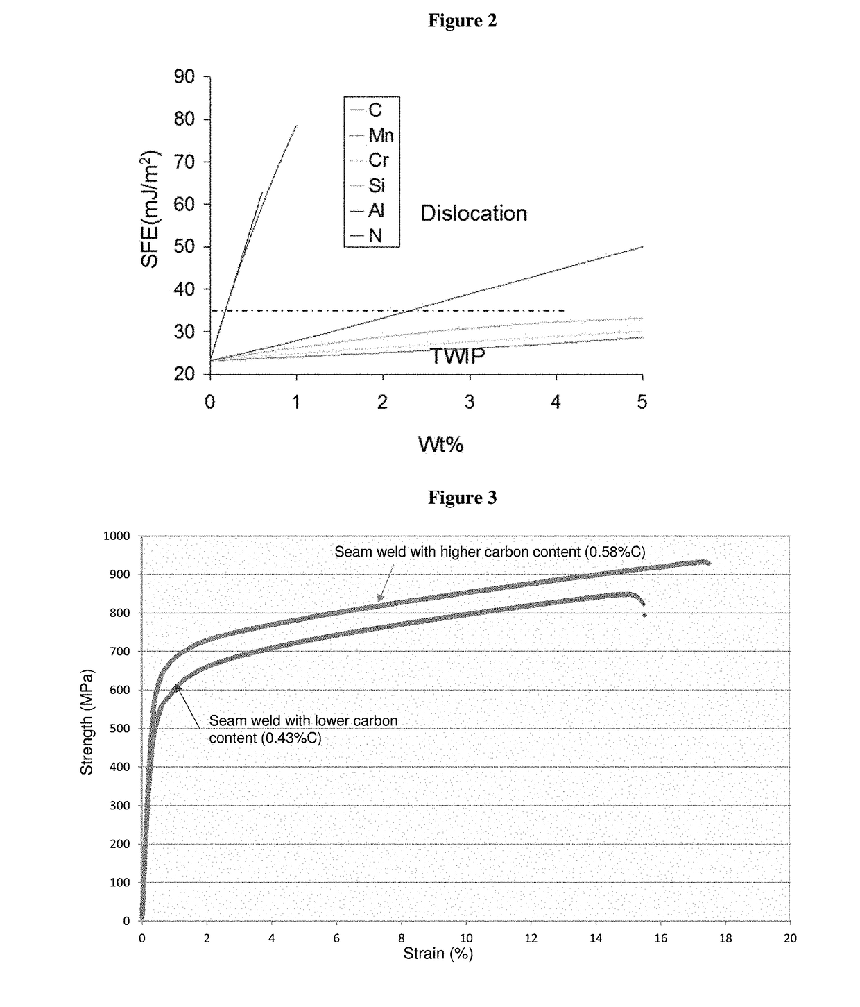
[0097]High manganese steel pipes of 24 to 30 inch in diameter with a pipe wall thickness of 19 mm to 20.6 mm were fabricated by submerged arc welding with two different levels of carbon content as shown in FIG. 3. Seam welding was performed under the following welding conditions: a current of 530-630 A and a voltage of 27-31 V, at a welding speed of 510-650 mm / min and heat input of 13-23 kJ / cm. The seam welding with higher carbon content shows increased yield and ultimate tensile strength over the weld metal with lower carbon content.

example 2

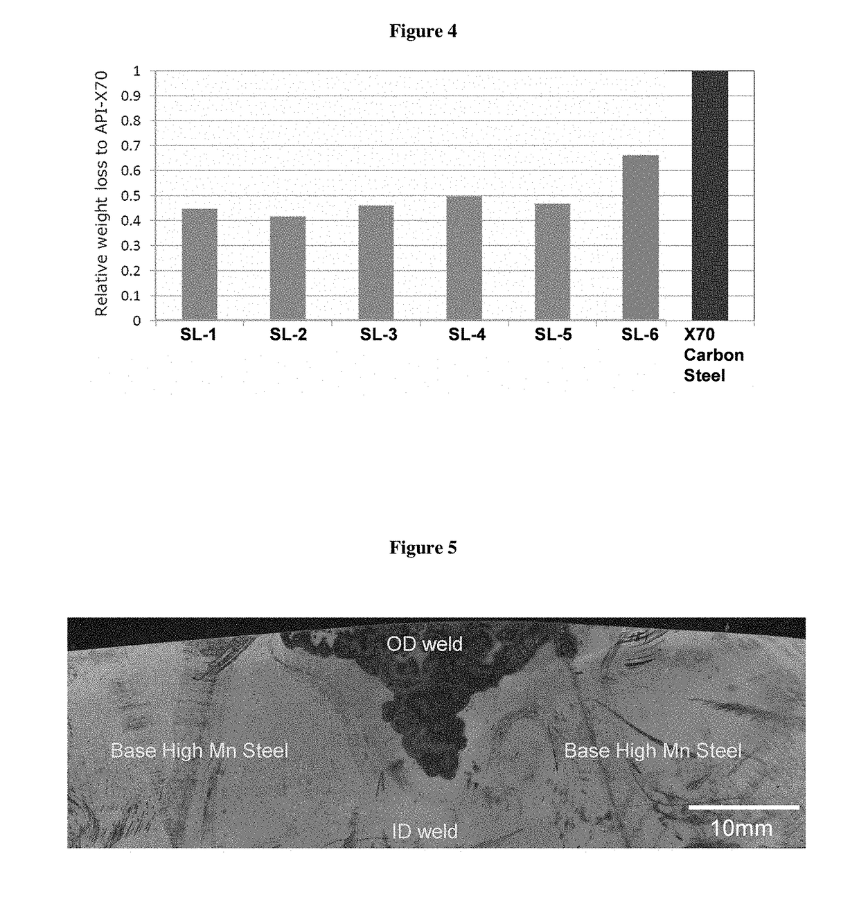
[0098]High manganese steel plates of 19 mm thickness were welded with six weld metals of varied weld metal chemistries as shown in Table 1. The abrasion wear resistance of each weld metal was evaluated rotating rubber wheel testing per ASTM G65. Weld metals with higher carbon content and enhanced alloying of Cr, Mo, and W (SL-1 through SL-5) shows improved wear resistance compared with that of lower carbon content weld metal (SL-6) and API X70 carbon steel as shown in FIG. 4.

TABLE 1Weld metal chemistriesWeld I.D.Nominal Weld Metal ChemistrySL-10.5C—19Mn—2.5Cr—1.2MoSL-20.5C—19Mn—2.5Cr—3MoSL-30.5C—19Mn—2.5Cr—2.2WSL-40.45C—19Mn—6Cr—1.5WSL-50.45C—19Mn—2.5Cr—0.07NSL-60.43C—17Mn—2.5Cr—0.5Mo

example 3

[0099]High manganese steel pipes of 24 to 30 inch in diameter with a pipe wall thickness of 19 mm to 20.6 mm were fabricated by submerged arc welding with two different levels of chromium alloying content between ID passes and OD passes as shown in Table 2. The seam weld coupons cut from the seam welded pipe were dipped in an aqueous solution simulating oil sands slurry pipe environment of 45° C. temperature, 1500 ppm NaCl, pH=8, and 8 ppm dissolved oxygen. As shown in FIG. 5, ID pass weld beads with higher Cr content than that of OD pass beads show less corrosion scale and better resistance to preferential weld corrosion.

TABLE 2Chemistries of weld and base high Mn steel from Inductively-Coupled Plasma Optical Emission Spectroscopy (ICP-OES).Weld I.D.CMnCrSiNiMoCuSPID Passes0.9617.92.920.340.040.270.460.0020.013OD Passes0.8118.62.670.590.030.620.530.0040.008HMS Base Steel1.1617.73.440.030.030.010.430.0020.013

[0100]Whereas the disclosure has been described principally in connection w...


PUM

PropertyMeasurementUnit
Fractionaaaaaaaaaa
Fractionaaaaaaaaaa
Percent by massaaaaaaaaaa

Abstract

Improved steel welds, article for making the same, and methods of making the same are provided. The present disclosure provides advantageous erosion, corrosion and / or cracking resistant weld metal. More particularly, the present disclosure provides high manganese (Mn) weld metal compositions having enhanced erosion, corrosion and / or cracking resistance, articles for the production of the high manganese weld metal compositions having enhanced erosion, corrosion, and / or cracking resistance, and methods for fabricating high manganese weld metal compositions having enhanced erosion, corrosion and / or cracking resistance.

Description

CROSS REFERENCE TO RELATED APPLICATIONS[0001]This application claims the benefit of and priority to U.S. Provisional Application Ser. No. 62 / 330,400 filed May 2, 2016, the disclosure of which is herein incorporated by reference in its entirety.BACKGROUND1. Field of the Discovery[0002]The present disclosure relates to improved steel compositions and methods of making the same, and more particularly, to high manganese (Mn) steel seam welded pipe having enhanced erosion-corrosion resistance, mechanical strength, and toughness of the seam weld zone and the methods to make the same. In particular, the high manganese steel seam weld zone that contains weld metal and the heat affected zone exhibit step-out erosion resistance, corrosion resistance, hydrogen embrittlement resistance, and stress corrosion cracking resistance in the oil sands slurry environment.2. Background Information[0003]In the following specification, the disclosure is described in the context of high manganese steel slur...

Claims


Application Information

Patent Timeline
IPC IPC(8): B23K35/30C22C38/44C22C38/42C22C38/02C22C38/00B23K35/02B23K9/23C22C38/58B23K9/18
CPCB23K35/3073B23K9/186B23K9/23B23K35/0261C22C38/002C22C38/44C22C38/42C22C38/02C22C38/58C22C38/22C22C38/24C22C38/26C22C38/20C22C38/38B23K35/362B23K35/368
Inventor JIN, HYUNWOOMA, NINGOZEKCIN, ADNANWASSON, ANDREW J.FAIRCHILD, DOUGLAS P.HAN, ILWOOKLEE, SANGCHULLEE, BONGKEUNLEE, JONGSUB
Owner POSCO
Learn More