
Medical/Surgical Implant

a technology for surgical implants and implants, applied in the field of implants, can solve the problems of significant soft tissue irritation, negative psychological effect of procedures on patients' well-being, undesirable breast appearance, etc., and achieve the effects of reducing necrosis and resorption of transplanted cells, reducing post-operative healing time, and improving patient well-being

Active Publication Date: 2017-09-14
KLINIKUM REKHTS DER IZAR DER TEKHNISHEN UNIV MYUNKHEN
View PDF29 Cites 11 Cited by
  • Summary
  • Abstract
  • Description
  • Claims
  • Application Information

AI Technical Summary

Benefits of technology

This patent aims to improve the process of reconstructing lost or damaged tissue using various techniques. The goal is to overcome common problems associated with current methods, such as poor cell or tissue engagement with connective tissue and vasculature, necrosis, and scar formation. The patent also aims to provide better outcomes for breast reconstruction and allow for larger amounts of transplant cells or tissue to be implanted. Additionally, the goal is to develop minimally invasive procedures for reconstructing tissue and organs.

Problems solved by technology

Such procedures have a negative psychological effect on the well-being of the patient.
The saline solution may also be replaced with silicone.However, controversy still exists with regard to the association of silicone-based implants with numerous health problems, such as formation of a rigid fibrous tissue surrounding the implant, causing significant soft tissue irritation via capsular contracture and giving, from a cosmetic point of view, an undesirable appearance to the breast.
Moreover, it has been found that siloxanes and platinum could leak out of such implants and their levels were elevated in the fatty tissues of a woman with such a leaking implant (Flassbeck et al.
When the expansion is complete, it is either replaced with a permanent saline- or silicone-based implant, or left inside.Perhaps the biggest disadvantage with using prosthetic implants is that of capsular contracture.
Multiple studies have demonstrated that inserting such an implant leads to a foreign body reaction resulting in the formation of a capsule of fibrous tissue around the implant.
This ultimately leads to an unnatural hemispherical appearance of the breast and restricted shoulder or arm movement.
This risk of capsular contracture also rises significantly when the breasts are irradiated subsequent to implantation.In addition, both types of implants may also be subject to rupture, displacement, deformation, chronic seroma, hematoma and loss of nipple sensation.
Because of such reasons, breast reconstruction using implants is not a completely sustainable solution.
Furthermore, lipotransfer of large amounts of adipose tissue bears the risk of adipose tissue necrosis owing to insufficient vascularisation—ultimately leading to formation of oil cysts.Thus, autologous fat transplantations yield poor results, with 40-60% reduction in graft volume owing to tissue resorption and necrosis.
Both cases may lead to necrosis of the flap tissue.
Other inherent risks include total / partial flap loss and abdominal bulge or hernia.
Over time, the scaffold degrades and the newly formed tissue takes its place.However, stem cell-based approaches also have several disadvantages impeding their clinical translation—ranging from problems with scaling up of tissue culture to requiring complex GMP-certified laboratories for tissue culturing.
Furthermore, it is challenging to efficiently vascularise large clinically relevant breast scaffolds using precursor cell induction techniques.

Method used


Image

  • Medical/Surgical Implant
  • Medical/Surgical Implant
  • Medical/Surgical Implant

Examples


example 1

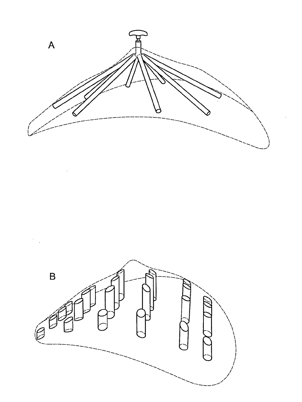
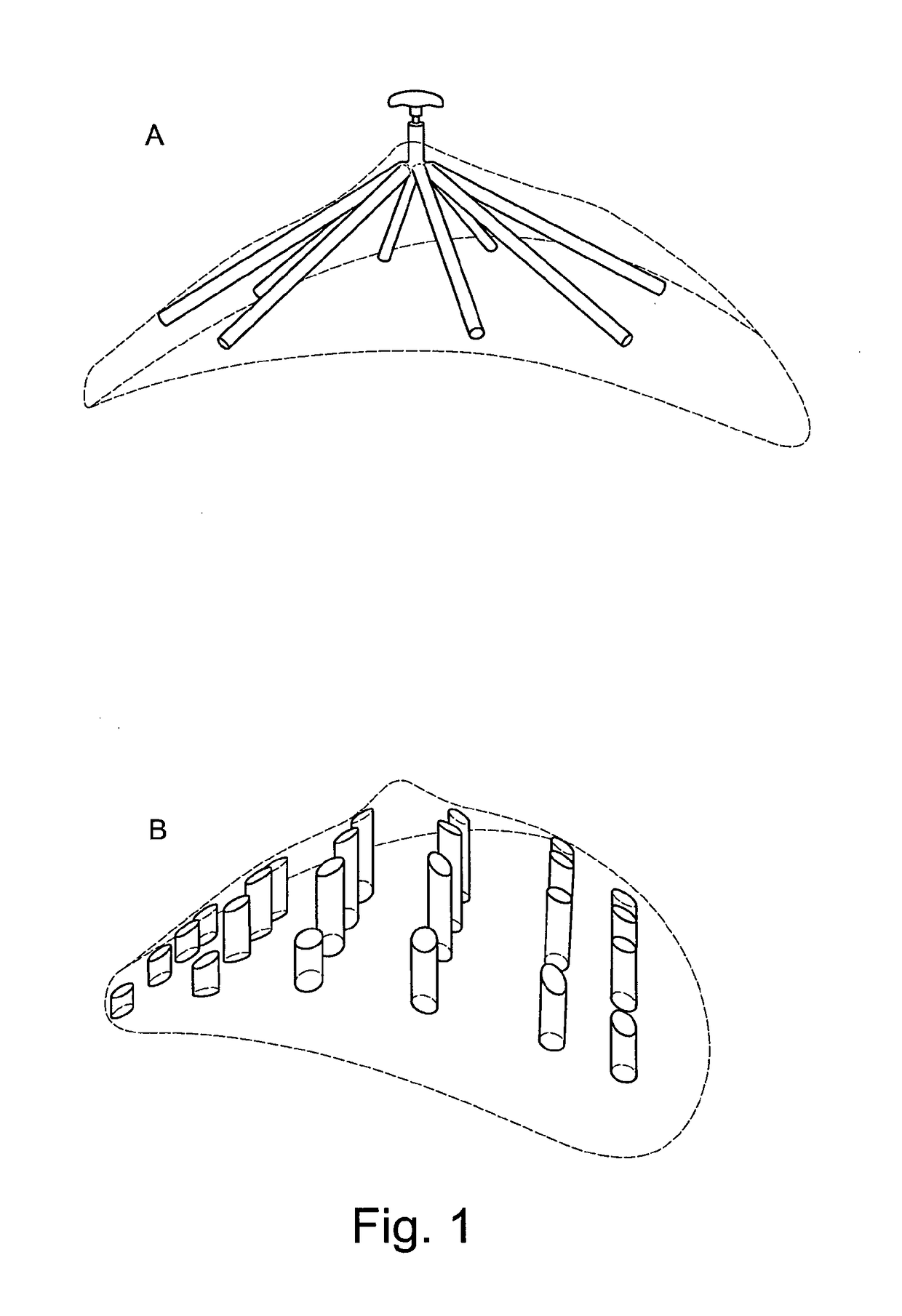
[0223]This example combines delayed fat injection with an acellular biodegradable scaffold. In this method of implantation, the scaffold is first implanted with no fat tissue into the implantation site. A fibrin clot is formed immediately after implantation of the scaffold from the hematoma caused by the surgical procedure (Henkel et al., 2013; Salgado et al., 2004). The clot consists of platelets embedded in a mesh of cross-linked fibres, together with a growth-factor rich cocktail of fibronectin, vitronectin and thrombospondin. The fibrin clot and the associated growth-factor cocktail may stimulate a strong angiogenic response and induce highly organised connective tissue to penetrate into the scaffold. After a fixed period of time, fat is isolated from a donor site within the patient's body and injected into the scaffold (see FIG. 12 for a visualisation of this concept). The amount of fat that can be harvested from the patient without encountering donor site morbidity depends on ...

example 2

[0274]Breast shaped scaffolds made of poly(D,L)-lactide polymer and containing voids and space-occupying structures essentially as shown in FIG. 21, scaled up to a scaffold volume of 125 cm3, were prepared. The scaffolds were fabricated with a 3D printer fitted with two extruders (one for printing poly(D,L)-lactide polymer for the scaffold structure, one for printing polylactic acid including a black dye for the space-occupying structures). Such a dual 3D print strategy also allows to prepare complex channel designs, if desired (e.g. a radially convergent design). Since the space-occupying structures are made of solid material, they are not degraded as quickly as the scaffold and thus are capable of preventing tissue / cell invasion within the rather short period of prevascularization in this example. With space-occupying structures made of an undegradable material, prevention of tissue / cell invasion is even better.

[0275]With such scaffolds, a pilot study was undertaken whereby n=6 sc...


PUM

PropertyMeasurementUnit
Structureaaaaaaaaaa
Sizeaaaaaaaaaa
Biocompatibilityaaaaaaaaaa

Abstract

The present invention relates to the field of implants. In particular, the present invention relates to an implant for tissue reconstruction which comprises a scaffold structure that includes a void system for the generation of prevascularized connective tissue with void spaces for cell and / or tissue transplantation. Moreover, the present invention relates to a method of manufacturing such an implant, to the internal architecture of such an implant, to a removal tool for mechanical removal of space-occupying structures from such an implant, to a kit comprising such an implant and such a removal tool, to a removal device for the removal of superparamagnetic or ferromagnetic space-occupying structures from such an implant, as well as to a guiding device for providing feedback to a surgeon during the procedure of introducing transplantation cells into the void spaces generated upon removal of space-occupying structures from such an implant.

Description

FIELD OF THE INVENTION[0001]The present invention relates to the field of implants. In particular, the present invention relates to an implant for tissue reconstruction which comprises a scaffold structure that includes a void system for the generation of prevascularized connective tissue with void spaces for cell or tissue transplantation. Moreover, the present invention relates to a method of manufacturing such an implant, to the internal architecture of such an implant, to a removal tool for mechanical removal of space-occupying structures from such an implant, to a kit comprising such an implant and such a removal tool, to a removal device for the removal of superparamagnetic or ferromagnetic space-occupying structures from such an implant, as well as to a guiding device for providing feedback to a surgeon during the procedure of introducing transplantation cells into the void spaces generated upon removal of space-occupying structures from such an implant.BACKGROUND OF THE INVE...

Claims


Application Information

Patent Timeline
IPC IPC(8): A61F2/12A61L27/58A61L27/50A61L27/44A61L27/28A61L27/54A61L27/56A61L27/18
CPCA61F2/12A61L2430/04A61L27/58A61L27/18A61L27/446A61L27/28A61L27/54A61L27/50A61F2002/0081A61F2002/009A61F2210/0004A61F2250/0063A61L2400/16A61L2300/416A61L27/56A61F2002/0086A61F2250/0059A61F2210/009C08L67/04A61F2/0077A61F2240/001
Inventor HUTMACHER, DIETMAR WERNERSCHANTZ, JAN-THORSTENWIGGENHAUSER, PAUL SEVERINCHHAYA, MOHIT PRASHANT
Owner KLINIKUM REKHTS DER IZAR DER TEKHNISHEN UNIV MYUNKHEN
Learn More