Backing Plate Obtained by Diffusion-Bonding Anticorrosive Metal and Mo or Mo Alloy, and Sputtering Target-Backing Plate Assembly Provided with Said Backing Plate

a technology of anticorrosion metal and diffusion bonding, which is applied in the direction of vacuum evaporation coating, coating, electric discharge tubes, etc., can solve the problems of warpage of target material, target material warpage, and deformation of target material, so as to prevent the corrosion of mo, reduce the warpage of sputtering target, and low thermal expansion

Active Publication Date: 2017-07-27
JX NIPPON MINING & METALS CO LTD
View PDF4 Cites 1 Cited by
  • Summary
  • Abstract
  • Description
  • Claims
  • Application Information

AI Technical Summary

Benefits of technology

[0020]The present invention relates to a backing plate formed mainly from Mo or a Mo alloy having a small coefficient of expansion to be bonded to a target made from a low thermal expansion material, and particularly relates to a backing plate in which an anticorrosive metal having a thickness corresponding to 1 / 40 to ⅛ of a total thickness of the backing plate is formed as a dense and strong layer on a surface of the Mo or Mo alloy backing plate, from which side the backing plate is cooled (cooling surface side), for preventing the corrosion of Mo being prone to corrosion with cooling water.
[0021]With the present invention, since a target formed from a low thermal expansion material and a Mo or Mo alloy backing plate having a similar thermal expansion coefficient are bonded, it is possible to reduce the warpage of sputtering targets as much as possible. It is thereby possible to form a uniform film across the entire substrate with minimal generation of particles.
[0022]Moreover, by providing a layer formed from an anticorrosive metal on the cooling surface side of molybdenum, the present invention is able to resolve the conventional problems such as contamination of the cooling water by black powdery rust generated due to the corrosion of molybdenum, and diffusion of rust in the clean room when removing the target.
[0023]Moreover, the present invention is also effective in addressing issues during sputtering, with regard to the strength, anticorrosive properties, and cooling capacity of the backing plate itself as well as the bonding strength of the backing plate and the target, as a result of performing anticorrosion treatment while ensuring the appropriate thickness of the molybdenum material having low thermal expansion, high thermal conductivity, and high strength.
[0024]The sputtering target that is consequently bonded via brazing yields superior effects of being able to achieve high power sputtering, reduce the percent defective due to uniform deposition, and improve the production efficiency. Moreover, the present invention is able to provide a sputtering target of high cleanliness which will not contaminate the cooling water of sputtering equipment and the surrounding environment such as the clean room.

Problems solved by technology

When producing a target formed from a low thermal expansion material, as the diameter becomes larger, there is a problem in that the difference in the thermal expansion between the target material and the backing plate material increases, and the target is prone to warpage.
Issues that become problematic during this kind of high power sputtering are the strength and cooling capacity (favorable thermal conductivity) of the backing plate itself and the bonding strength of the backing plate and the target.
In particular, when brazing a low thermal expansion target material and a generally used copper backing plate by heating the target material and the backing plate to a temperature that is equal to or higher than the melting point of a brazing material and then cooling the target material and the backing plate, the target material will become warped (deformed) in the shape of a protrusion since the copper backing plate having a greater coefficient of expansion will shrink more, and this warpage (deformation) becomes a factor that obstructs the formation of a uniform film during sputtering.
Moreover, the difference in shrinkage of both materials also becomes a problem in deteriorating the bonding strength at the bonded interface.
Nevertheless, when a molybdenum backing plate is used and cooling water is caused to flow so that it directly comes into contact with the molybdenum backing plate, rust of molybdenum oxide will easily arise, and contaminate the surrounding environment of the sputtering equipment.
However, Patent Document 2 offers no description whatsoever regarding the means for improving the anticorrosive properties.
Nevertheless, while various methods may be considered for producing the Mo / Cu composite material, Patent Document 3 offers no description regarding the specific method of solution.
Moreover, Patent Document 3 offers no description regarding anticorrosive properties or the thickness of Mo / Cu, and it is considered that the intended requirement specification of the sputtering target cannot be achieved merely by compounding Mo and Cu.

Method used


Image

  • Backing Plate Obtained by Diffusion-Bonding Anticorrosive Metal and Mo or Mo Alloy, and Sputtering Target-Backing Plate Assembly Provided with Said Backing Plate
  • Backing Plate Obtained by Diffusion-Bonding Anticorrosive Metal and Mo or Mo Alloy, and Sputtering Target-Backing Plate Assembly Provided with Said Backing Plate
  • Backing Plate Obtained by Diffusion-Bonding Anticorrosive Metal and Mo or Mo Alloy, and Sputtering Target-Backing Plate Assembly Provided with Said Backing Plate

Examples


example 1

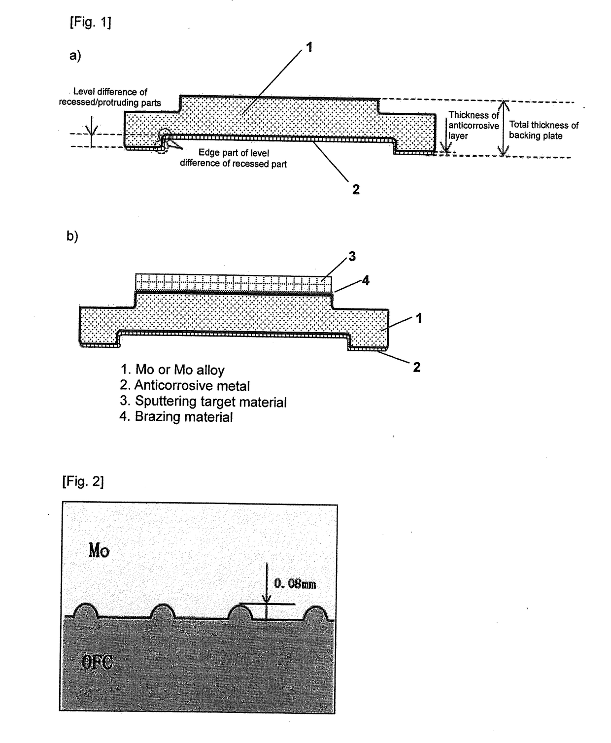
[0052]A specific example of the present invention is now explained with reference to FIG. 1 and FIG. 2. Mo having a purity of 3N was processed into a disk shape having a diameter of 540 mm and a total thickness of 20 mm, and a recess having a diameter of 480 mm and a depth of 4 mm was formed on one surface to prepare a material 1 having a concave side that becomes the base of the backing plate (refer to FIG. 1a), FIG. 1b)). Here, the edge of the level difference part was rounded to R1.5, and grooves having a depth of 0.08 mm were regularly formed on the overall Mo bottom face to yield an anchor effect during bonding (refer to FIG. 2).

[0053]Next, oxygen-free copper (OFC) 2 as the anticorrosive metal was processed such that the edge of the protruding part is R1.5, the diameter is 480 mm, the outer diameter is 540 mm, and the total thickness is 7 mm (refer to FIG. 1a), FIG. 1b)). Furthermore, OFC was processed such that the recessed side is over tolerance and the protruding side is min...

example 2

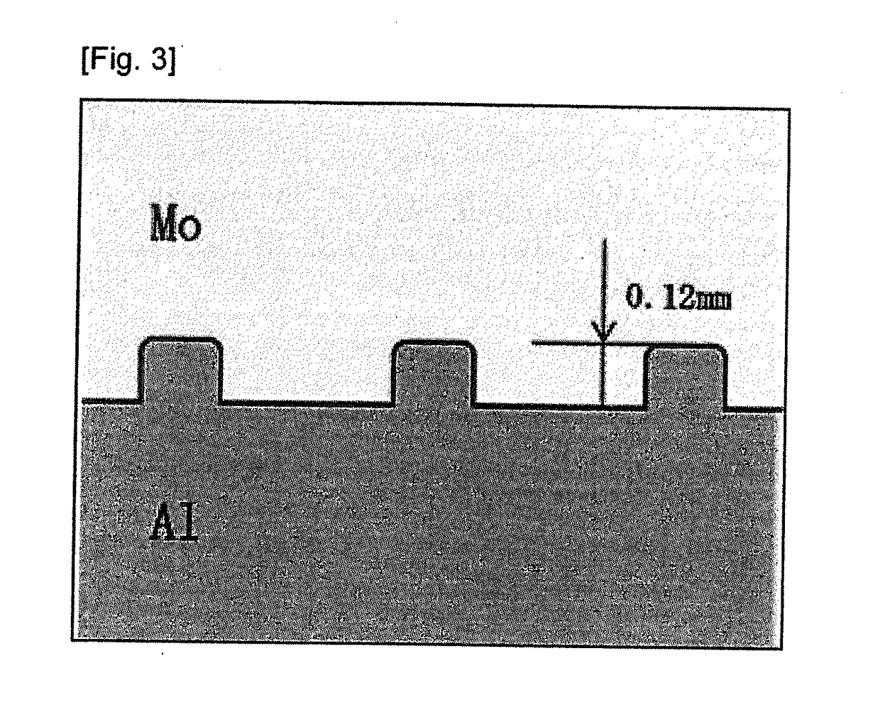
[0061]A specific example of the present invention is now explained with reference to FIG. 1 and FIG. 3. Mo having a purity of 3N was processed into a disk shape having a diameter of 540 mm and a total thickness of 18 mm, and a recess having a diameter of 480 mm and a depth of 3 mm was formed on one surface to prepare a material having a concave side that becomes the base of the backing plate (refer to FIG. 1). Here, the edge of the level difference part was rounded to R1.5, and grooves having a depth of 0.12 mm were regularly formed on the overall Mo bottom face to yield an anchor effect during bonding.

[0062]Next, aluminum (5052 alloy) as the anticorrosive metal was processed into a bowl shape such that the edge of the protruding part is R1.5, the diameter is 480 mm, the outer diameter is 600 mm, and the total thickness is 21 mm (refer to FIG. 1 and FIG. 3).

[0063]The tolerance of the engaging parts were set to be the same as Example 1. The recess and protrusion of these two material...


PUM

PropertyMeasurementUnit
diameteraaaaaaaaaa
depthaaaaaaaaaa
thicknessaaaaaaaaaa

Abstract

Provided is a backing plate obtaining by bonding an anticorrosive metal and Mo or a Mo alloy, wherein the backing plate comprises, on a surface of the Mo or Mo alloy backing plate to be cooled (cooling surface side), a layer having a thickness corresponding to 1 / 40 to ⅛ of a total thickness of the backing plate and formed from an anticorrosive metal obtained by bonding one or more types of metals selected from among Cu, Al and Ti, or an alloy thereof. Additionally provided is a sputtering target-backing plate assembly obtained by bonding the foregoing Mo or Mo alloy backing plate and a target formed from a low thermal expansion material.Particularly in semiconductor applications, reductions in size have progressed and control of particles during sputtering has become stricter. The present invention aims to resolve the problem of warpage of sputtering targets formed from low thermal expansion materials and problems occurring with respect to the anticorrosive properties of Mo or Mo alloy backing plates.

Description

TECHNICAL FIELD[0001]The present invention relates to a backing plate to be used when using a low thermal expansion material as a sputtering target material, and particularly a backing plate obtained by diffusion-bonding an anticorrosive metal and Mo or a Mo alloy and capable of preventing warpage (deformation) during the bonding of a sputtering target and a backing plate or during sputtering, as well as a sputtering target-backing plate assembly provided with such a backing plate.BACKGROUND ART[0002]In recent years, various thin films are now required in the application of semiconductor devices, and demands of low thermal expansion materials such as silicon, germanium, and carbon are also increasing. Moreover, as the diameter of silicon wafers to be used as the substrate increases to 200 mm, 300 mm, and 450 mm, sputtering targets also grow in size, and there are needs to produce large-diameter targets also based on the foregoing low thermal expansion materials.[0003]Meanwhile, the ...

Claims


Application Information

Patent Timeline
Patent Type & Authority Applications(United States)
IPC IPC(8): H01J37/34
CPCH01J37/3417H01J37/3435C22C27/04C23C14/3407
Inventor TAKAMURA, HIROSHISUZUKI, RYO
Owner JX NIPPON MINING & METALS CO LTD
Why Eureka
Try Eureka