
Cutting insert, cutting tool comprising such an insert and methods for producing and repairing such a tool

a technology of cutting tools and inserts, which is applied in the field of cutting tools, can solve the problems of high manufacturing and repair costs of these cutting tools, complex and costly installation of brazing like this, and the relative high cost of these cutting tools is essentially linked

Active Publication Date: 2017-01-05
DIAMONDE
View PDF5 Cites 2 Cited by
  • Summary
  • Abstract
  • Description
  • Claims
  • Application Information

AI Technical Summary

Benefits of technology

This patent is about a new type of cutting tool that can be used on wood base composite materials. The tool has cutting inserts that are attached to a tool body at a low temperature, reducing the risk of the tool body becoming too hot and losing its strength. The tool is also designed to allow for easy replacement of worn-out cutting inserts, without requiring a high-temperature furnace. Additionally, the patent discusses the use of high-temperature brazing to bond ceramic materials to metal substrates, and how this technique can be used to attach ceramic materials to a tool body even if the materials cannot be directly attached to the tool body. This improves the overall strength and durability of the tool.

Problems solved by technology

The relatively high cost of these cutting tools is essentially linked to the use of diamonds.
Mandatorily, this results in high manufacturing and repair costs for these cutting tools.
The implementation of brazing like this requires a complex and costly installation.
Furthermore, the high brazing temperature can cause the de-tempering of the steel, resulting in the alteration of the mechanical properties of the material and, thereby, of the cutting tool.
Repairing such a tool is difficult and expensive because the cutting inserts cannot be de-brazed individually.
These are lengthy and complex operations to implement.
In addition, the reliability of the bond between the cutting inserts and the tool body can only be mastered with difficulty.
Indeed, the dissimilarity of the physical properties of the cermet cutting inserts and of the substrate very often causes differential thermal connotation which can favour the separation of the cutting insert while damaging the ceramic material.
Similarly, the bond obtained at low temperature between the cermet and the metal layer obtained by electrolytic deposit is hardly satisfactory because, at low temperature, the cermet does not absorb the metal.
This method concerns specifically a nitride which is part of the non-oxide ceramics and which is also a compound formed from and agglomerate crystal powder in a metal matrix; it will not allow application to cutting tools for highly abrasive materials such as wood, in particular reconstituted wood or particleboard composites.
But these nitrites may be unsuitable for cutting tools working under the brutal conditions encountered in the machining of highly abrasive materials.

Method used


Image

  • Cutting insert, cutting tool comprising such an insert and methods for producing and repairing such a tool
  • Cutting insert, cutting tool comprising such an insert and methods for producing and repairing such a tool
  • Cutting insert, cutting tool comprising such an insert and methods for producing and repairing such a tool

Examples


example 2

[0109]A ceramic plate consisting of 100% zirconia-yttria 3Y—Zr02 is lined on one face with a coat of metal paint.

[0110]A metal plate of nickel steel C45 of the same size is also lined on one face with a coat of metal paint.

[0111]The metallized face of the ceramic plate is then attached in vacuum at 780° C. to the metallized face of the metal tungsten plate by brazing using a silver-copper alloy comprising more than 50% silver by volume.

[0112]The assembly obtained in this way is then cut into cutting inserts by means of a jet of water under pressure, a laser or a diamond disk.

[0113]Inserts each having a cutting insert are then attached together by their substrate to the tool body by brazing at atmospheric pressure and at a temperature included between 560° C. and 620° C. This brazing is carried out using an electromagnetic inductor and a silver-copper brazing alloy comprising less than 60% silver by volume.

example 3

[0114]A ceramic plate is used comprising 90% alumina α-A1203 and 10% zirconium Zr02 wind on one of its faces with a coat of metal paint and a metal tungsten plate WC-30Co of the same size with a coat of metal paint on one face.

[0115]The metallized face of the ceramic plate is then attached in vacuum at 800° C. to the metallized face of the metal tungsten plate by brazing using a silver-copper alloy comprising more than 50% silver by volume.

[0116]The assembly obtained in this way is then cut into cutting inserts by means of a jet of water under pressure, a laser or a diamond disk.

[0117]Inserts each having a cutting insert are then attached together by their substrate to the tool body by brazing at atmospheric pressure and at a temperature included between 560° C. and 620° C. This brazing is carried out using an electromagnetic inductor and a silver-copper brazing alloy comprising less than 60% silver by volume.


PUM

PropertyMeasurementUnit
Temperatureaaaaaaaaaa

Abstract

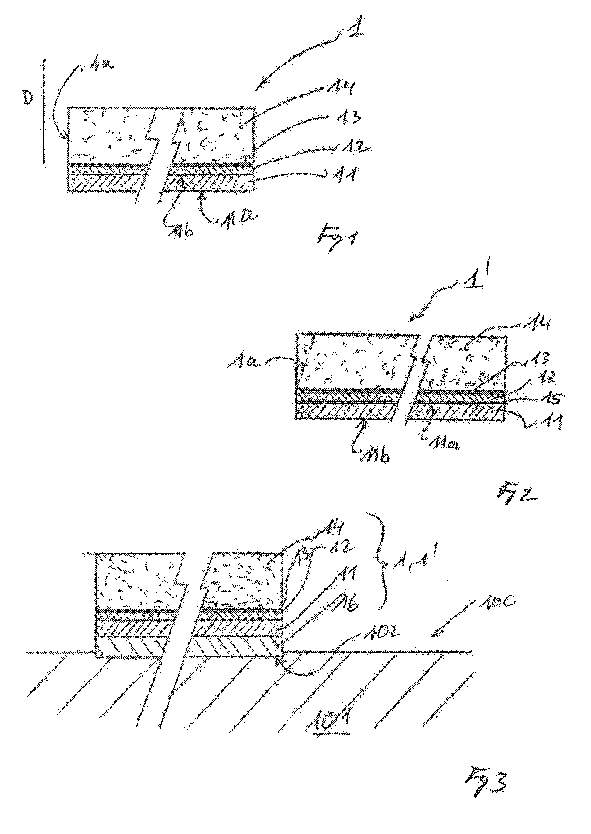
The invention relates to an insert brazed on a body of cutting tools (101), consisting of: a metal substrate (11), in the form of plates, having a surface for attachment to the tool body; a high-temperature, brazing, alloy layer (12); an intermediate layer; and a ceramic plate (14). The brazing alloy layer connects the metal substrate (11) of the ceramic plate (14) via the metal layer (13). A low-temperature brazing layer (1) connects the insert (1, 1′) to the body of the tool (101).

Description

DISCLOSURE OF THE INVENTION[0001]This invention concerns the general technical field of cutting tools used for machining or cutting wood and / or wood-based composite materials and derivatives.[0002]More particularly, the invention concerns a process for manufacturing cutting tools and a process for repairing such cutting tools.[0003]This invention also concerns the manufacturing of cutting inserts attached to the tool body.STATE OF THE TECHNIQUE[0004]The cutting tools used for working wood-based composite materials have inserts often made of a diamond powder mechanically linked with a substrate, for instance, metal carbide. The cutting inserts are then cut from this subassembly in order to be brazed to a tool body.[0005]Brazing is at low temperature and at atmospheric pressure, using a brazing alloy, for instance based on the copper and silver.[0006]Electric sharpening is then performed, for instance by the electroerosion of the cutting inserts attached to the tool body.[0007]The rel...

Claims


Application Information

Patent Timeline
IPC IPC(8): B23K31/02B23D61/02B23D61/04C04B37/02B23K1/20B23K35/30B23P15/28C04B37/00B23C5/18B23K1/00
CPCB23K31/025C04B2237/60B23D61/028B23D61/04B23K1/0008B23K1/203B23K35/3006B23P15/28C04B37/006C04B37/026B23C2224/04B23C2226/18B23C2240/08B23K2201/20B23K2203/18B23K2203/52C04B2237/125C04B2237/343C04B2237/348C04B2237/36C04B2237/406B23C5/18B23K35/0222B23K35/0233B23K35/0238B23K35/0244B23K35/30B23K2101/20B23K2103/172B23K2103/18B23K2103/26B23K2103/52B32B9/005B32B9/041B32B15/18B32B2255/205C04B2235/6581C04B2237/122C04B2237/126C04B2237/127C04B2237/401C04B2237/55C04B2237/72
Inventor GRUNDER, TIMOTHEEPIQUEREZ, ANNE
Owner DIAMONDE
Learn More