
Vehicle

a technology for vehicles and motors, applied in the field of vehicles, can solve the problems of reducing or deteriorating the controllability of electric power generated from the power supply unit, and achieve the effects of reducing the running performance of the vehicle, curtailing or preventing, and reducing the output torque of the drive motor

Active Publication Date: 2016-07-14
TOYOTA JIDOSHA KK
View PDF11 Cites 21 Cited by
  • Summary
  • Abstract
  • Description
  • Claims
  • Application Information

AI Technical Summary

Benefits of technology

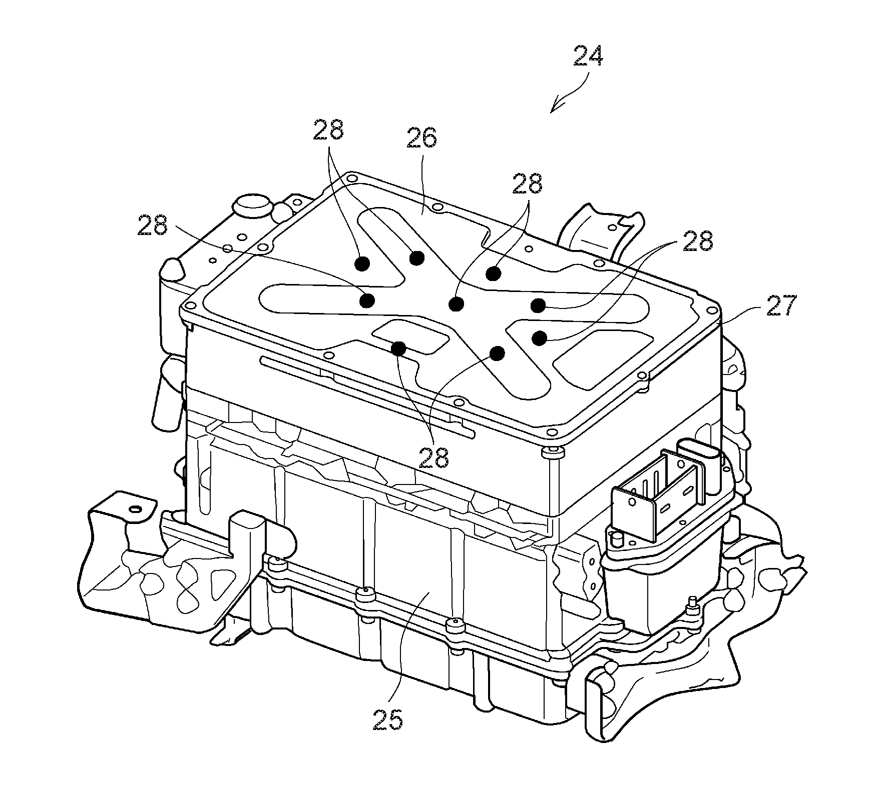
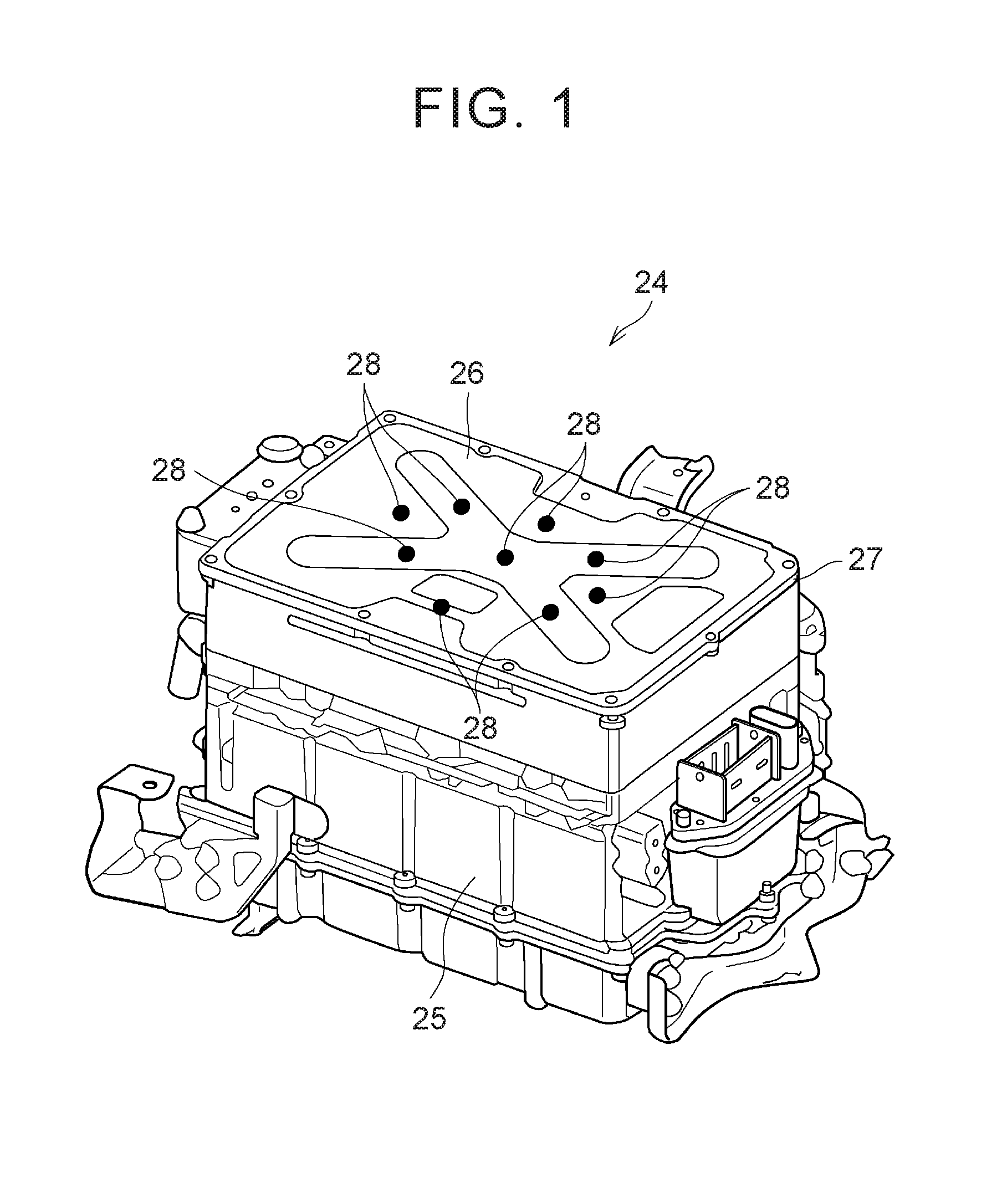
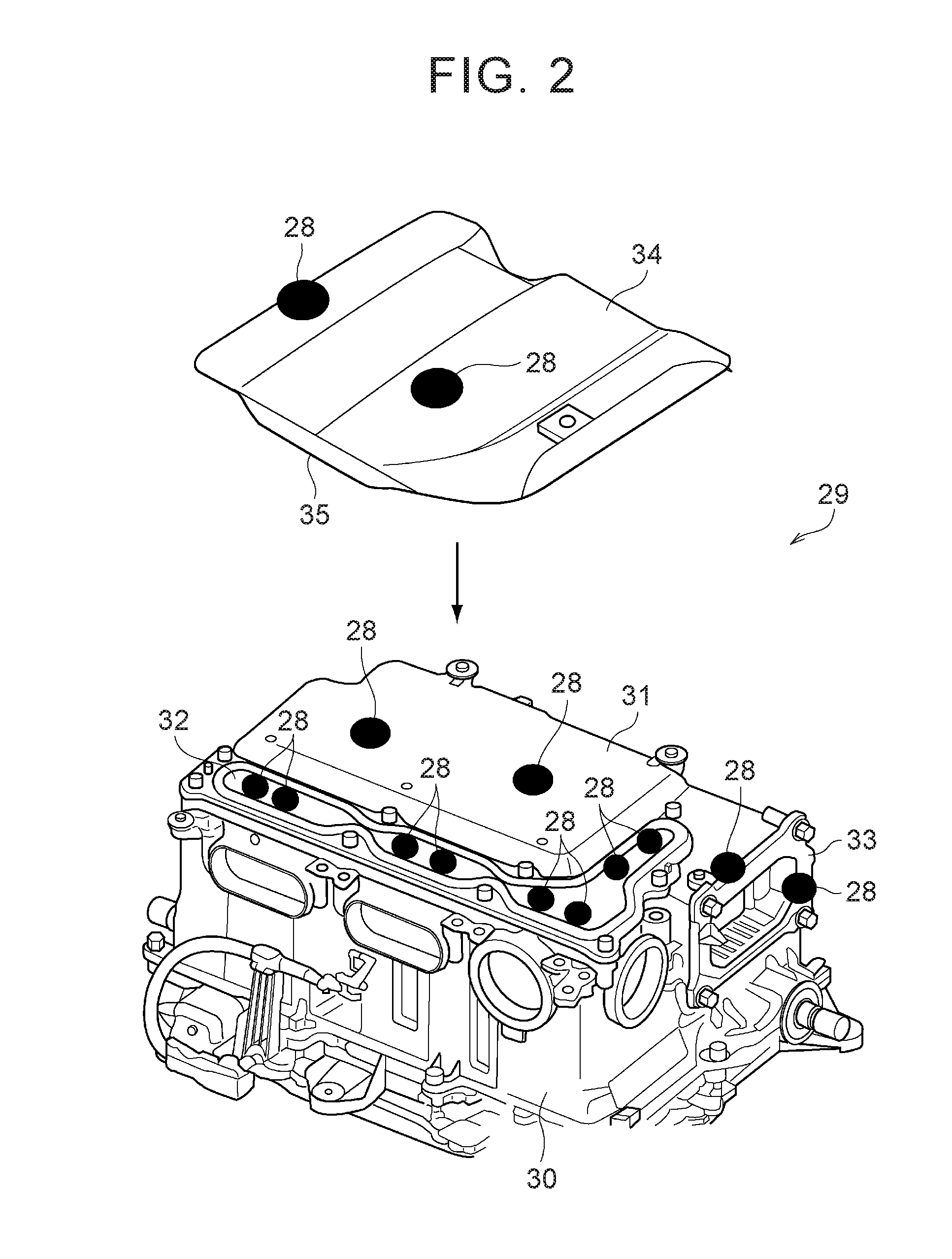
The present invention provides a vehicle that can neutralize and eliminate static electricity of a power unit connected to a drive motor. This is achieved by using a self-discharge-type static eliminator that generates negative air ions in outside air based on the positive potential of the member. The static eliminator reduces the potential difference between the member and the inside air of the case main body, which in turn reduces static charges transferred from the inside air to the member. This results in the inverter and converter being less likely or even unlikely to be electrostatically charged, and the controllability of the inverter and converter being less likely or even unlikely to be influenced by static electricity. The vehicle also includes a fixed frame and a cover member connected to the fixed frame, and the self-discharge-type static eliminator is provided on the connecting portion between the cover member and the fixed frame or the connecting portion between the fixed frame and the vehicle body. This eliminates static charges on the connecting portion, reducing the potential difference between the cover member and its inside air, and preventing degradation of the running performance of the vehicle.

Problems solved by technology

Thus, the controllability of electric power generated from the power supply unit may be reduced or deteriorated due to an influence of the static electricity.

Method used


Image

  • Vehicle
  • Vehicle
  • Vehicle

Examples


Embodiment Construction

[0027]Vehicles to which this invention can be applied include a hybrid vehicle having an engine and a motor as drive power sources, or a vehicle including a drive motor (which will be simply referred to as “motor”), for example, an electric vehicle having only the motor as a drive power source. One example of the motor is a three-phase synchronous electric motor configured such that its output torque and rotational speed are controlled according to the magnitude and frequency of a current passed through the motor. The synchronous motor is configured to generate electric power when it is forcibly rotated by external force. In the meantime, wheels are formed of an insulating material (or a material having a small electric conductivity), such as rubber, and the vehicle body and the road surface are held in an insulated condition.

[0028]FIG. 6 shows one example of an electric circuit that supplies electric power to a motor 1. In the example shown in FIG. 6, a battery 2 and a capacitor 3 ...


PUM


Abstract

A vehicle includes a power control unit having at least one of an inverter and a converter, a drive motor that produces torque for running the vehicle when electric power is supplied from the power control unit to the drive motor, a vehicle body kept insulated from a road surface, a case main body in which the power control unit is housed, a member that is connected to the case main body where the member is insulated from the case main body, or in a condition in which electric resistance is large, and a static eliminator that neutralizes and eliminates positive charges on the member and lowers a positive potential of the member, by self-discharge for producing negative air ions in outside air according to the positive potential of the member that is electrostatically charged.

Description

INCORPORATION BY REFERENCE[0001]The disclosure of Japanese Patent Application No. 2015-004288 filed on Jan. 13, 2015 including the specification, drawings and abstract is incorporated herein by reference in its entirety.BACKGROUND OF THE INVENTION[0002]1. Field of the Invention[0003]Embodiments of the present invention relates to a vehicle including a power control unit or a power supply that supplies electric power to a drive motor.[0004]2. Description of Related Art[0005]A battery that supplies electric power to accessories installed on a vehicle is described in Japanese Patent Application Publication No. 2010-177128 (JP 2010-177128 A). A lid of the battery is formed of a resin material. An electrostatic induction member is attached to the lid that causes static charges from a person who contacts the battery to flow to the vehicle body. The electrostatic induction member is attached to such a position that gas accumulated inside the battery, or gas discharged from the battery, is ...

Claims


Application Information

Patent Timeline
IPC IPC(8): B60R16/06H02P23/28H02P31/00B60L11/18B60L3/00
CPCB60R16/06H02P31/00H02P23/28B60L11/1851H01M50/20B60L3/0069B60L15/007H02P27/06H02M7/003H05K9/0067B60L1/003B60L3/003B60L3/0084B60L7/14B60L15/20B60L15/2009B60L2220/14B60L2240/34B60L2240/36B60L2240/421B60L2240/423B60L2270/145B60L50/51B60L58/21B60L58/26B60L50/66B60L50/64Y02E60/10Y02P70/50H05K7/14322B62B3/16B62B3/002B62B2202/12B60L3/0046H05K7/1432B60L58/14B60L58/10B60L58/12Y02T10/64Y02T10/70Y02T10/72
Inventor TANAHASHI, TOSHIOKANEHARA, YOJIYAMADA, KOSHIOSHIRO, YUTA
Owner TOYOTA JIDOSHA KK
Learn More