
Planar transmission-line permittivity sensor and calibration method for the characterization of liquids, powders and semisolid materials

a technology of permittivity sensor and transmission line, which is applied in the direction of dielectric property measurement, resistance/reactance/impedence, instruments, etc., can solve the problems of inconvenient use of open-ended coaxial-line probes to characterize the dielectric anisotropy of materials, large sample preparation, and inability to conveniently use closed transmission lines to measure. , to achieve the effect of rapid permittivity measuremen

Active Publication Date: 2016-06-30
UNITED STATES OF AMERICA
View PDF11 Cites 7 Cited by
  • Summary
  • Abstract
  • Description
  • Claims
  • Application Information

AI Technical Summary

Benefits of technology

The present invention provides a sensor apparatus that can quickly measure the permittivity of materials, such as liquid, powders, and semisolids, with minimal sample preparation. This is achieved by using planar transmission lines and a calibration method that can determine the material permittivity directly from the measured microwave scattering parameters. The invention can also be used to accurately and simply measure the anisotropic dielectric properties of materials, which can be useful in determining physical properties of interest of foods, agricultural products, and other biological and non-biological materials. Overall, the invention allows for faster and more accurate non-destructive characterization of materials.

Problems solved by technology

In addition, the open-ended coaxial-line probe cannot be conveniently used to characterize the dielectric anisotropy of materials, (Clerjon and Damez, Meas. Sci. Technol., Volume 18, 1038-1045, 2007).
However, the closed structures of many of these transmission line types, (e.g., waveguide and coaxial line) mean that considerable sample preparation is necessary.
Closed transmission lines cannot be conveniently used to measure the permittivity of materials outside a laboratory.
However, a significant limitation of these approaches is that neither allows ∈* to be directly calculated from γ, and numerical iterative methods must be used.
A small uncertainty in these dimensions can result in considerable uncertainty in the measured ∈*.
If the planar lines are fabricated with low-cost equipment, the dimensional uncertainty is often large.
These methods require that the sample be carefully prepared and are mechanically time consuming.
Moreover, for biological materials such as muscle tissue, it can be difficult to precisely identify the direction of the grain.
If the sample is not properly aligned, this approach does not provide an accurate measurement of the permittivity tensor.
The high level of precision means that such an approach is not well suited to measurements outside the laboratory.
While the configuration (Huynen et al, October 2001, supra) is suitable for permittivity measurements of substrate materials, it is not mechanically suited to the measurement of materials placed on the planar line because considerable sample preparation is necessary to ensure that the two samples are identical, apart from a known length difference.
In addition, the method adopted for the numerical extraction of the material permittivity requires significant computational resources.
Numerical techniques, however, require considerable computational resources in order to obtain accurate results and therefore they are not particularly suited for rapid permittivity measurements in industrial settings.
However, as demonstrated (Roelvink and Trabelsi, 2012 IEEE International Symposium on Antennas and Propagation and USNC-URSI National Radio Science Meeting, Chicago, Ill., 2012; herein incorporated by reference in its entirety), small dimensional uncertainties, particularly in regions where the fields are relatively concentrated, can result in large measurement uncertainty.
If low-cost equipment is used to manufacture the planar transmission-line sensor, the dimensional uncertainty can be large.

Method used


Image

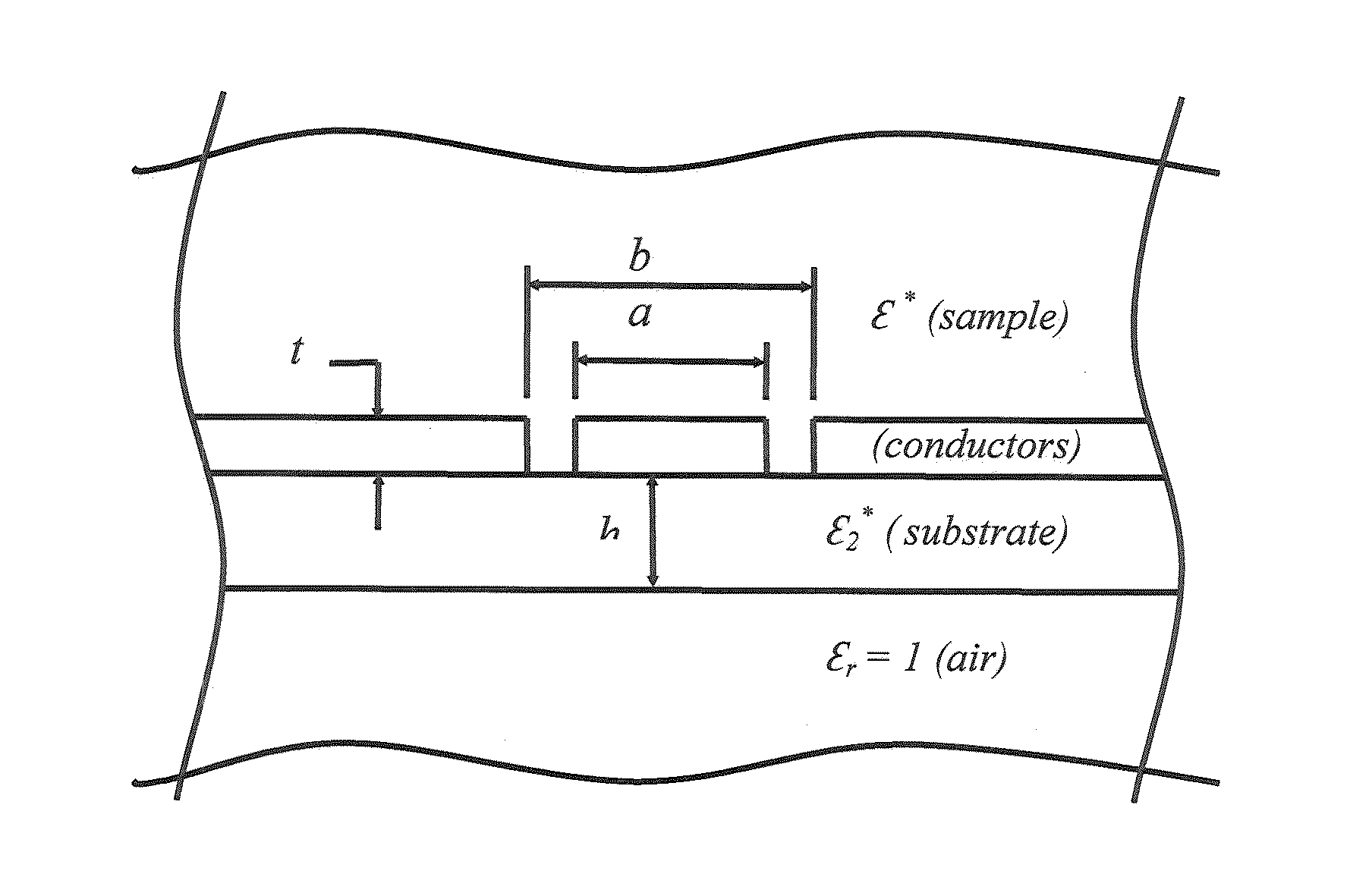
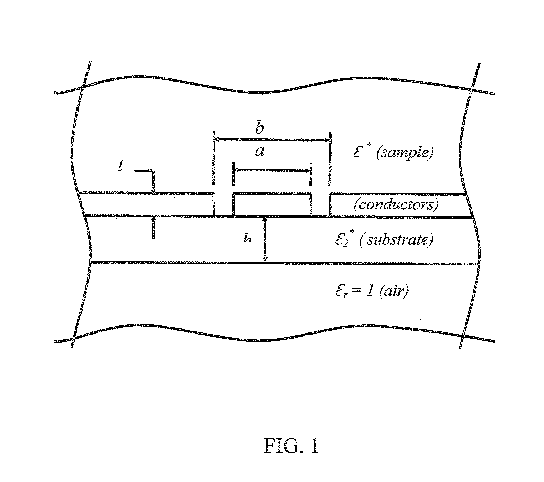
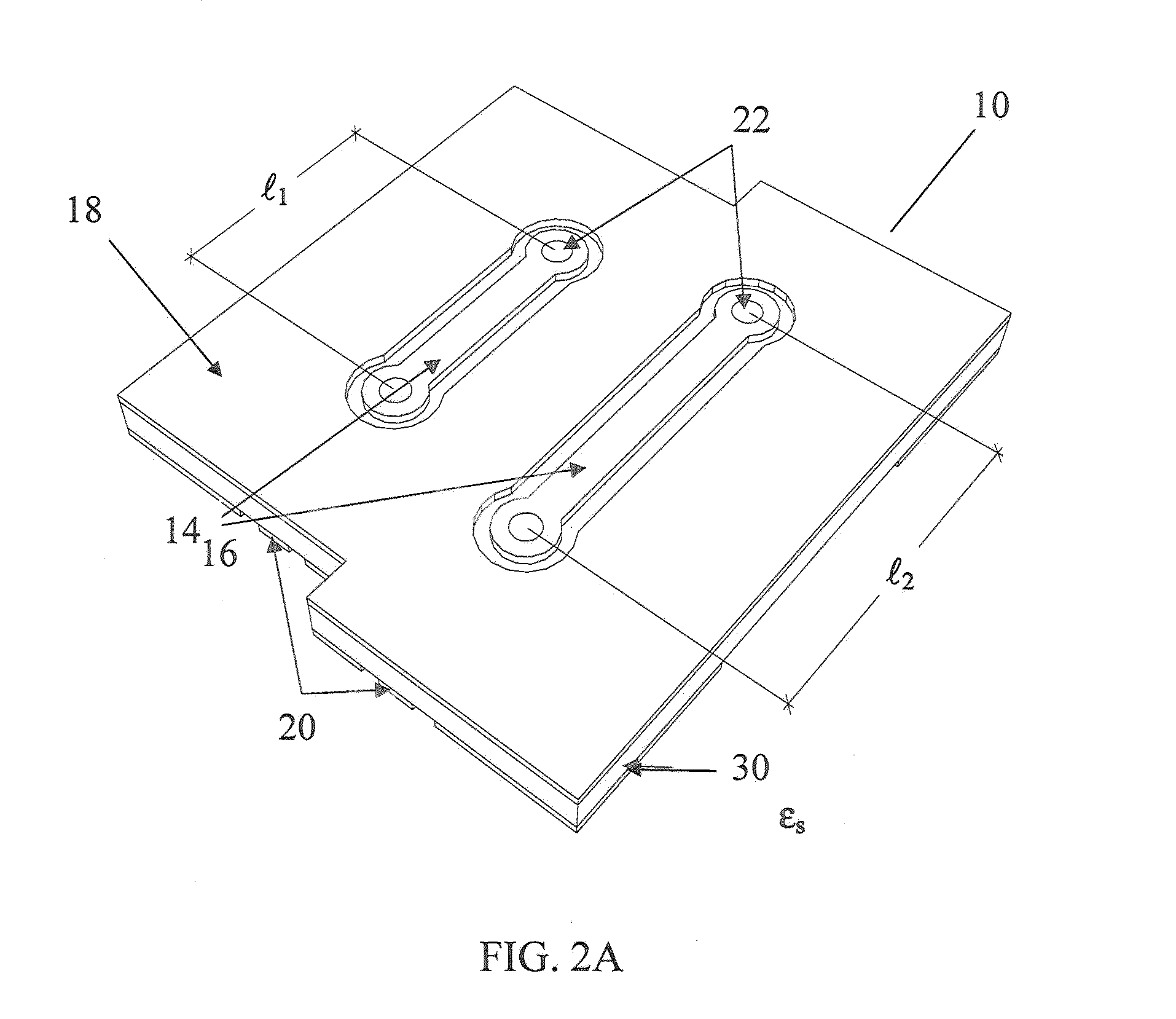
  • Planar transmission-line permittivity sensor and calibration method for the characterization of liquids, powders and semisolid materials
  • Planar transmission-line permittivity sensor and calibration method for the characterization of liquids, powders and semisolid materials
  • Planar transmission-line permittivity sensor and calibration method for the characterization of liquids, powders and semisolid materials

Examples


example 1

Permittivity Measurements on Liquids

[0052]This example demonstrates how to measure the permittivity of liquids with the present invention. The scattering parameters were obtained for three aqueous solutions of ethanol and three reference liquids placed on the CPW lines over the frequency range 0.5−5 GHz with an Agilent E5071C ENA series network analyzer connected to each of the coaxial connectors as shown in FIG. 5. The scattering parameters without any sample present, ∈*=1, were also measured. The aqueous solutions of ethanol (purity ≧99.5%) were mixed by mass with distilled water. Permittivity results were then calculated by using the technique described in Section 1. The permittivity results were compared to measurements obtained with an Agilent 85070B coaxial-line probe and reference data for each liquid (Kaatze, 2007, supra; Green, Measurements of the dielectric relaxation spectra of nine liquids and binary mixtures at 20° C. and microwave frequencies, in Proceedings of the Con...

example 2

Anisotropy Measurements on Biological Materials

[0057]Because of the difficulty in producing samples with known anisotropic dielectric properties, the anisotropy measurement technique (Section 3) is first demonstrated by using numerical simulation software (COMSOL Multiphysics www.comsol.com). The two-port scattering parameters of two lengths, 20- and 30-mm, of material-loaded conductor-backed CPW transmission line 14 and 16 at 2 GHz were obtained from simulations. The propagation constant, γ(θ), was obtained from the simulated scattering parameters by using the multiline technique.

[0058]The calibration constants in (15) were first obtained from simulations of two materials with known homogeneous ∈* (Roelvink et al, 2013, supra). Several combinations of ∈⊥*, and ∈∥* were considered and for each combination θ was varied from zero to π / 2 in π / 4 steps (one quadrant was sufficient due to symmetry). The samples were orientated as shown in FIG. 3. Note, however, that the technique describe...

example 3

Permittivity Measurement of Biological Materials of Different Moisture Contents

[0063]Measurements using the CPW were performed on samples of sawdust and gelatin of different moisture content at 25° C. The CPW was connected to an E5071C ENA Network Analyzer and a TRL calibration and two standards (air and distilled water at 25° C.) were used to calibrate the system. Results of the measurements at different frequencies are tabulated below for each material and each moisture content:

TABLE 1Dielectric properties of sawdust at 5.7% moisture contentFrequency, GHz122.45345∈′1.331.301.311.291.291.28∈″0.0370.0440.0280.0360.0160.028

TABLE 2Dielectric properties of sawdust at 13.1% moisture contentFrequency, GHz122.45345∈′1.681.591.581.561.531.50∈″0.160.150.140.150.120.12

TABLE 3Dielectric properties of sawdust at 21.4% moisture contentFrequency, GHz122.45345∈′2.382.272.222.182.132.03∈″0.230.290.310.320.310.31

TABLE 4Dielectric properties of sawdust at 32.0% moisture contentFrequency, GHz122.4534...


PUM

PropertyMeasurementUnit
dielectric constantaaaaaaaaaa
permittivityaaaaaaaaaa
phaseaaaaaaaaaa

Abstract

A low cost planar transmission line sensor and simple calibration method for measuring the complex permittivity of materials with minimal sample preparation over a wide band of radio- and microwave frequencies. The sensor is also used for measuring anisotropic dielectric properties of materials with a defined grain.

Description

REFERENCE TO RELATED APPLICATIONS[0001]This application claims the benefit of U.S. Provisional Patent Application Ser. No. 62 / 043,659, filed Aug. 29, 2014 entitled “Permittivity Planar Transmission-Line Sensor and Calibration Method for the Characterization of Liquids, Powders, and Semisolid Materials”. The U.S. Provisional Patent Application Ser. No. 62 / 043,659 is herein incorporated by reference in its entirety.FIELD OF THE INVENTION[0002]The present invention relates to a sensor apparatus and a calibration method for measuring the complex permittivity of liquids, powders, and semisolid materials with planar transmission lines at radio- and microwave-frequencies. Furthermore the present invention relates to a method for measuring the anisotropic dielectric properties of materials with the sensor apparatus.BACKGROUND OF THE INVENTION[0003]The permittivity of a material describes the relationship between electric flux density and an applied electric field. Permittivity is a function...

Claims


Application Information

Patent Timeline
Patent Type & Authority Applications(United States)
IPC IPC(8): G01R27/26G01R35/00G01N27/22
CPCG01R27/2617G01R35/005G01N27/221G01N22/00
Inventor ROELVINK, JOCHEM T.TRABELSI, SAMIR
Owner UNITED STATES OF AMERICA
Learn More