A particle size sensor for metallic powders

a technology of metallic powder and particle size sensor, which is applied in the direction of particle size analysis, measurement devices, instruments, etc., can solve the problems of difficult to accurately determine other powder characteristics, difficult to determine the particle size distribution of powdered materials, and high cost of the process

Inactive Publication Date: 2019-09-19
RENISHAW PLC
View PDF0 Cites 0 Cited by
  • Summary
  • Abstract
  • Description
  • Claims
  • Application Information

AI Technical Summary

Benefits of technology

The patent describes a way to non-destructively gather information about the size of metal powder particles in real-time, which is useful in determining the properties of the powder over time. The sensor is simple and can be easily integrated into additive manufacturing equipment, allowing for easy monitoring of the powder quality. It requires minimal sample preparation and can operate at high temperatures. The sensor allows for non-destructive testing of the powder, which means the tested powder can be reused in the manufacturing process.

Problems solved by technology

However, using the temperature as a measure of the absolute absorption has many difficulties.
Firstly, the precise power delivered to the sample must be calculated and this may not be trivial due to the complex loading and changing condition of the applicator caused by the heated powder.
Also, accurate determination of other powder characteristics will likely be difficult.
Determination of the particle size distribution for a powdered material is currently a relatively expensive or inconvenient process.
In an industrial setting, a survey using scanning electron microscopy (SEM) is usually prohibitively expensive.
Laser diffraction is the standard measurement used but this usually requires that the powder is well-dispersed in liquid, a process which in metals is prone to error due to its high density.
Furthermore, these systems require significant ongoing maintenance and replenishment of consumables which makes them unattractive for many applications.

Method used


Image

  • A particle size sensor for metallic powders
  • A particle size sensor for metallic powders
  • A particle size sensor for metallic powders

Examples


example

[0065]Theoretical Considerations and Simulation

[0066]The complex magnetic dipole moment for an individual spherical particle is derived as2

m=2πa3H0((μ+2)(1-kacot(ka)-μ(ka)2)(μ-1)(1-kacot(ka)-μ(ka)2))(1)

[0067]where a is the particle radius, H0 is the applied magnetic field strength, ε is the internal sphere permittivity, μ is the internal sphere permeability and the wavelength

k=ωɛμc.

Electrical conductivity σ is introduced by making ε complex, i.e. by considering ε=ε1−jσ / ωε0, where the imaginary part dominates the real part ε1 for materials considered to be weakly conducting, and certainly so for materials considered to be metallic.

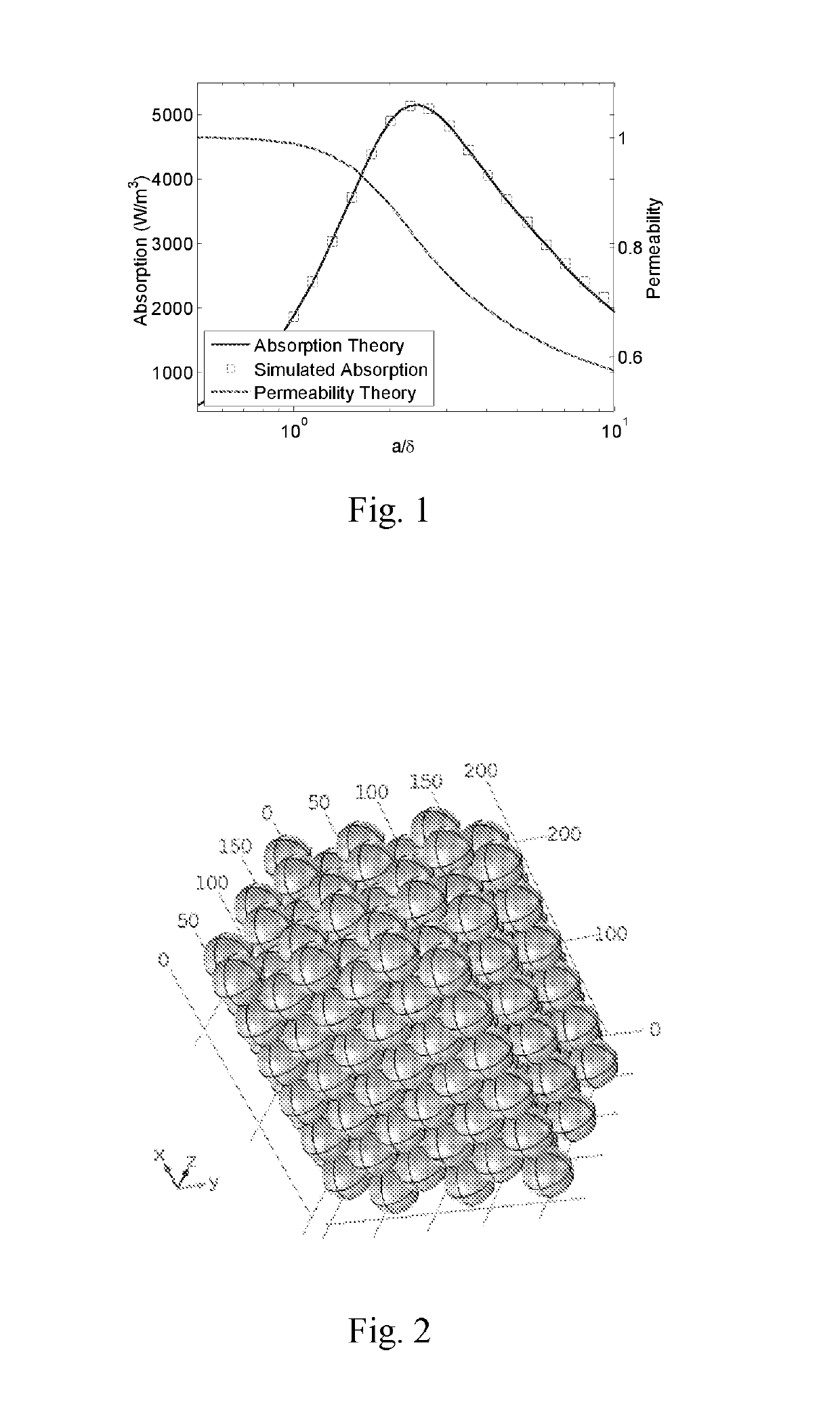
[0068]This leads to simplified expressions for the power absorbed per unit volume and the real part of the relative permeability for a non-magnetic conducting powder as

〈PM〉=34ωμ0H02Im(1+3cot(ka)ka-3(ka)2)(2)μ1=1-12Re(1+3cot(ka)ka-3(ka)2)(3)

[0069]Considering the large skin depth limit, a / δ<<1 we see that for small particles

limaδ→0〈PM〉=120ω2μ02a2σH02∝ω2a2σ(4)...


PUM

PropertyMeasurementUnit
electrical sizeaaaaaaaaaa
heightaaaaaaaaaa
internal radiusaaaaaaaaaa

Abstract

A particle size sensor for metallic powder includes a microwave cavity or waveguide, the microwave cavity or waveguide including a microwave source for generating microwaves within the microwave cavity or waveguide, a microwave receiver for detecting microwaves generated within the cavity or waveguide, a sample insertion point for receiving a sample of the metallic powder and an analyser arranged to determine a particle size for the metallic powder from receiver signals generated by the receiver.

Description

FIELD OF INVENTION[0001]This invention concerns a particle size sensor for metallic powders. This invention has particular, but not exclusive, application to use of the particle size sensor in an additive manufacturing apparatus and measuring a particle size of metallic powder recovered from a processing chamber of an additive manufacturing apparatus.BACKGROUND[0002]Since the first demonstration of sintering a metal powder body by microwave radiation1, efforts to understand the energy absorption of conducting metal powders has been ongoing. A variety of studies have taken a first principles approach to the theoretical understanding of absorption of an individual particle within both electric and magnetic fields2,3,4. It is accepted that, for any practical size of particles which are considered to be metallic on the basis of a high value of electrical conductivity, magnetic absorption via eddy current loss is much greater than loss in an equivalent electric field and this has been de...

Claims


Application Information

Patent Timeline
Patent Type & Authority Applications(United States)
IPC IPC(8): G01N15/02
CPCG01N15/0266G01N2015/0096G01N15/02
Inventor PORCH, ADRIANCLARK, NICHOLAS
Owner RENISHAW PLC
Why Eureka
Try Eureka