
Ceramic matrix composites and methods for producing ceramic matrix composites

a ceramic matrix and composite technology, applied in the field of ceramic matrix composites, can solve the problems of higher matrix cracking stress, load shifting from the matrix to the fiber,

Active Publication Date: 2016-04-21
ROLLS ROYCE CORP
View PDF6 Cites 7 Cited by
  • Summary
  • Abstract
  • Description
  • Claims
  • Application Information

AI Technical Summary

Benefits of technology

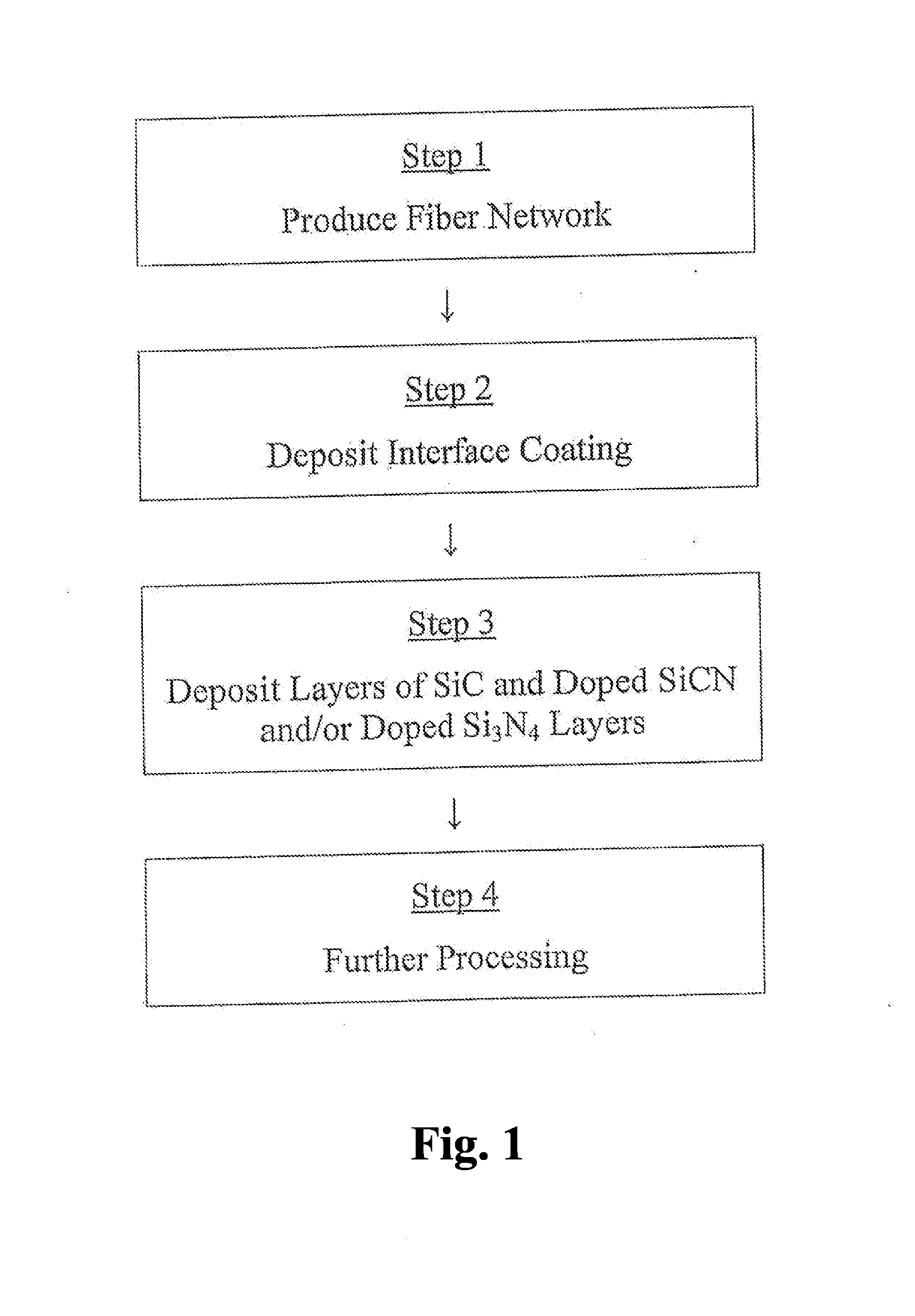
The patent describes a method for producing a ceramic matrix composite with embedded fibers. The method involves depositing a matrix material with a first component and a second component in a desired relationship to the fibers. This can be achieved by depositing the first component in an amount greater than its stoichiometric amount in relation to the second component. The resulting composite has a creep rate that is lower than that of the fibers. The method can also involve depositing an interface layer between the fibers and the matrix, or heat treating the composite. The ceramic matrix composite produced using this method has improved performance in terms of its thermal and mechanical properties.

Problems solved by technology

However, if the fiber is more creep resistant than the matrix, the matrix will begin to creep first and to a greater extent, which results in the load shifting from the matrix to the fiber.
The differential creep rates also result in a higher matrix cracking stress.

Method used


Image

  • Ceramic matrix composites and methods for producing ceramic matrix composites
  • Ceramic matrix composites and methods for producing ceramic matrix composites
  • Ceramic matrix composites and methods for producing ceramic matrix composites

Examples


example 2

[0040]A preform for a low pressure turbine blade for a gas turbine engine is produced from an aluminum containing silicon carbide fiber, such as Tyranno SA3 fiber produced by Ube Industries, Ltd. of Tokyo, Japan. The preform is approximately 30% fiber volume. An Si doped boron nitride interface coating approximately 0.8 um thick is applied to the fiber preform. The addition of Si to the BN coating improves oxidation resistance. Other interface coatings can be applied to achieve the same results. An SiC coating approximately 8 um to approximately 12 um thick is applied to the preform by CVI. The coating includes either about 10% to about 20% Si in excess of stoichiometric amounts or about 10% to about 20% C in excess of stoichiometric amounts. Aluminum is introduced during CVI through the chlorination of approximately 99.9% pure Al. This results in aluminum inclusion between about 0.05% and about 2% in the SiC deposit. The CMC matrix is then subjected to SiC and carbon powder slurry ...

example 3

[0041]A preform for a low pressure turbine blade for a gas turbine engine is produced from a silicon carbide fiber, such as a ceramic grade (CG) Nicalon fiber produced by Nippon Carbon Company, Ltd. of Tokyo, Japan. The preform is approximately 40% fiber volume. A boron doped SiC layer of approximately 0.1 um to approximately 0.2 um is deposited on the preform by CVI. An Si doped boron nitride interface coating approximately 0.8 um thick is then applied. The boron doped SiC layer improves bonding between the fibers and the Si doped boron nitride layer. Other intermediate interface coatings can be applied to achieve the same results. An SiC coating approximately 4 um to approximately 6 um thick is applied to the preform by CVI. The coating includes either about 10% to about 20% Si in excess of stoichiometric amounts or about 10% to about 20% C in excess of stoichiometric amounts. Oxygen and nitrogen are introduced during CVI by the introduction of air to form an Si, C, O and N deposi...


PUM

PropertyMeasurementUnit
pressureaaaaaaaaaa
temperatureaaaaaaaaaa
thickaaaaaaaaaa

Abstract

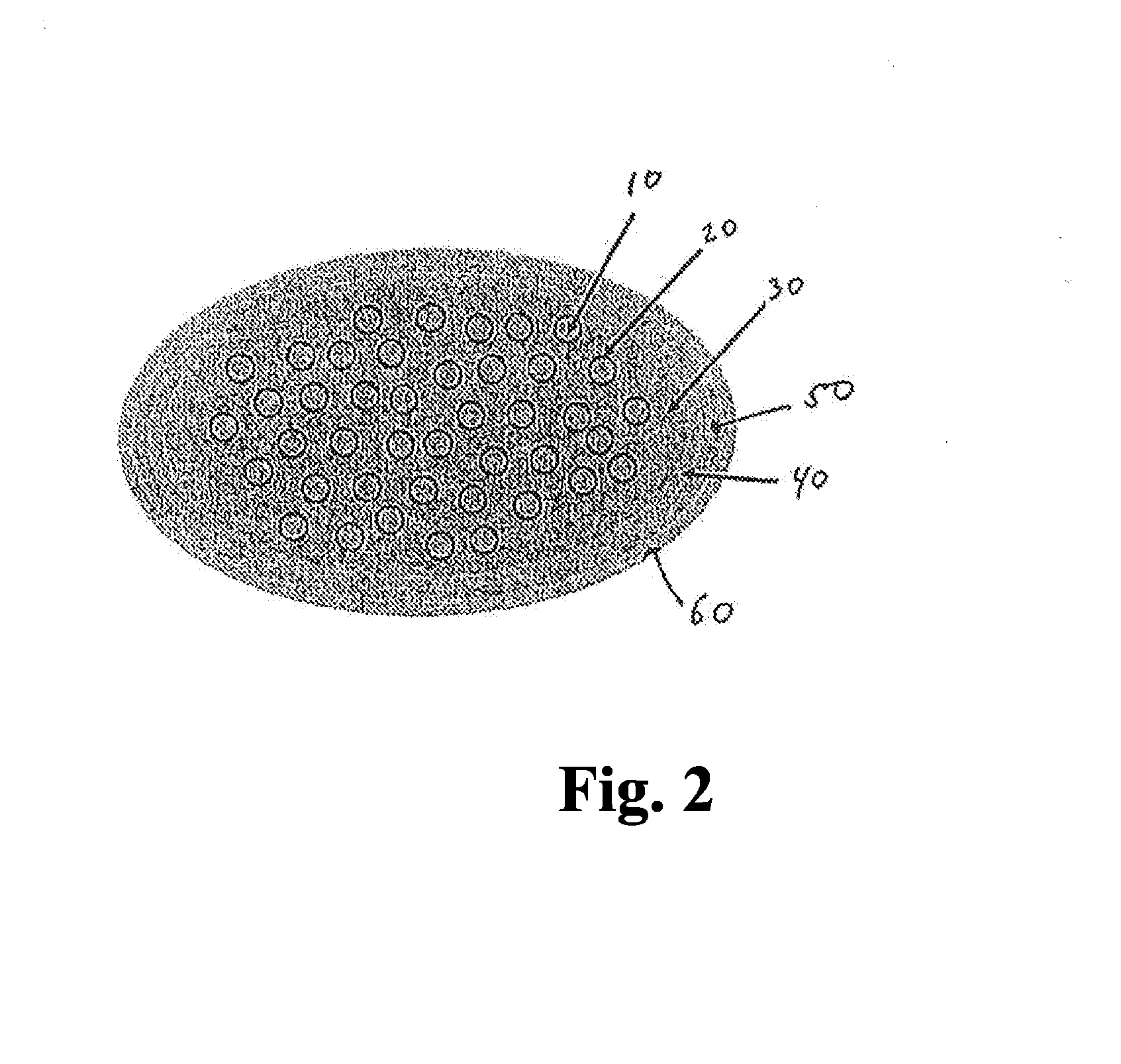
A ceramic matrix composite includes a plurality of fibers embedded in a matrix. The composition of the matrix is selected to achieve a desired relationship between the mechanical and thermal properties of the matrix and the fibers.

Description

RELATED APPLICATIONS[0001]This application is related to and claims priority to U.S. Provisional Patent Application Ser. No. 61 / 787,235, filed on Mar. 15, 2013 entitled “Ceramic Matrix Composites and Methods for Producing Ceramic Matrix Composites.” The subject matter disclosed in that provisional application is hereby expressly incorporated into the present application in its entirety.FIELD OF THE DISCLOSURE[0002]The present disclosure relates generally to ceramic matrix composites, and more specifically to ceramic matrix composites in which the thermal and mechanical properties of the matrix and those of the fiber are matched in a desired relationship by manipulation of the main matrix components and / or the introduction of additional elements into the matrix.BACKGROUND[0003]Ceramic Matrix Composites (CMS's) are materials that include ceramic fibers embedded in a ceramic matrix. CMC's typically exhibit desirable mechanical, chemical and physical properties at high temperatures. For...

Claims


Application Information

Patent Timeline
Patent Type & Authority Applications(United States)
IPC IPC(8): C04B41/45C23C16/32C04B41/87C04B41/00C04B41/50C04B41/52
CPCC04B41/4584C04B41/5059C04B41/5064C04B41/457C04B41/52C04B41/87C04B2235/3826C04B41/0072C23C16/325C04B2235/614C04B2235/616C04B2235/5244C04B2235/386C04B41/009C04B35/573C04B35/591C04B35/6269C04B35/62863C04B35/62868C04B35/62884C04B35/62894C04B35/62897C04B35/80C04B2235/422C04B2235/465C04B2235/483C04B2235/6581C04B2235/79C04B2235/96C04B2235/9607
Inventor LAZUR, ANDREW J.CHAMBERLAIN, ADAM L.
Owner ROLLS ROYCE CORP
Learn More