Photoluminescent NANO composite material and method of fabricating the same
a composite material and photoluminescent technology, applied in the field of nanomaterials, can solve the problems of high surface energy, insufficient coordination number of surrounding atoms, and inability to ignore the number and effect of surface atoms, and achieve the effects of low toxicity, fast and easy operation, and low cos
- Summary
- Abstract
- Description
- Claims
- Application Information
AI Technical Summary
Benefits of technology
Problems solved by technology
Method used
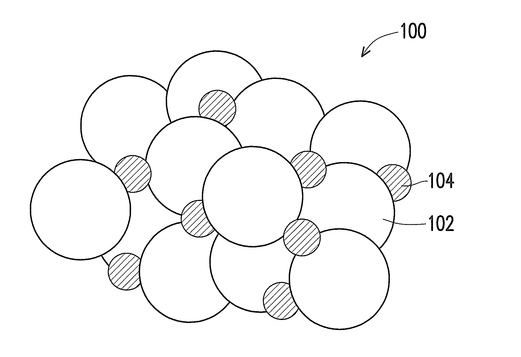
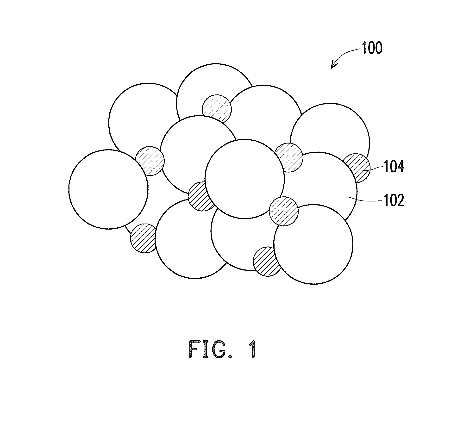
Image

Examples
experimental example 1
Fabrication of Graphene Quantum Dot Powder
[0069]First, a graphene quantum dot solution was prepared with the same method as comparative example 1. Then, after the graphene quantum dot solution of comparative example 1 was diluted 50 folds with double distilled water, the graphene quantum dot solution of comparative example 1 was left in an incubator at 30° C. for 12 hours. A white precipitate was thus obtained, and after high-speed centrifugation (1006 g, 3000 rpm, 10 minutes) was performed, the supernatant was taken out. Redissolution was then performed with 15 mL of deionized water, and then cleaning via purification was performed twice. Lastly, after centrifugation (1006 g, 3000 rpm, 10 minutes), the white precipitate in the lower layer was taken out and placed in an oven at 60° C. for 60 minutes to dry, thereby obtaining the graphene quantum dot powder of experimental example 1. An analysis with an energy-dispersive spectroscope shows that the powder has the elements of carbon, ...
experimental example 2
Fabrication of Graphene Quantum Dot Powder
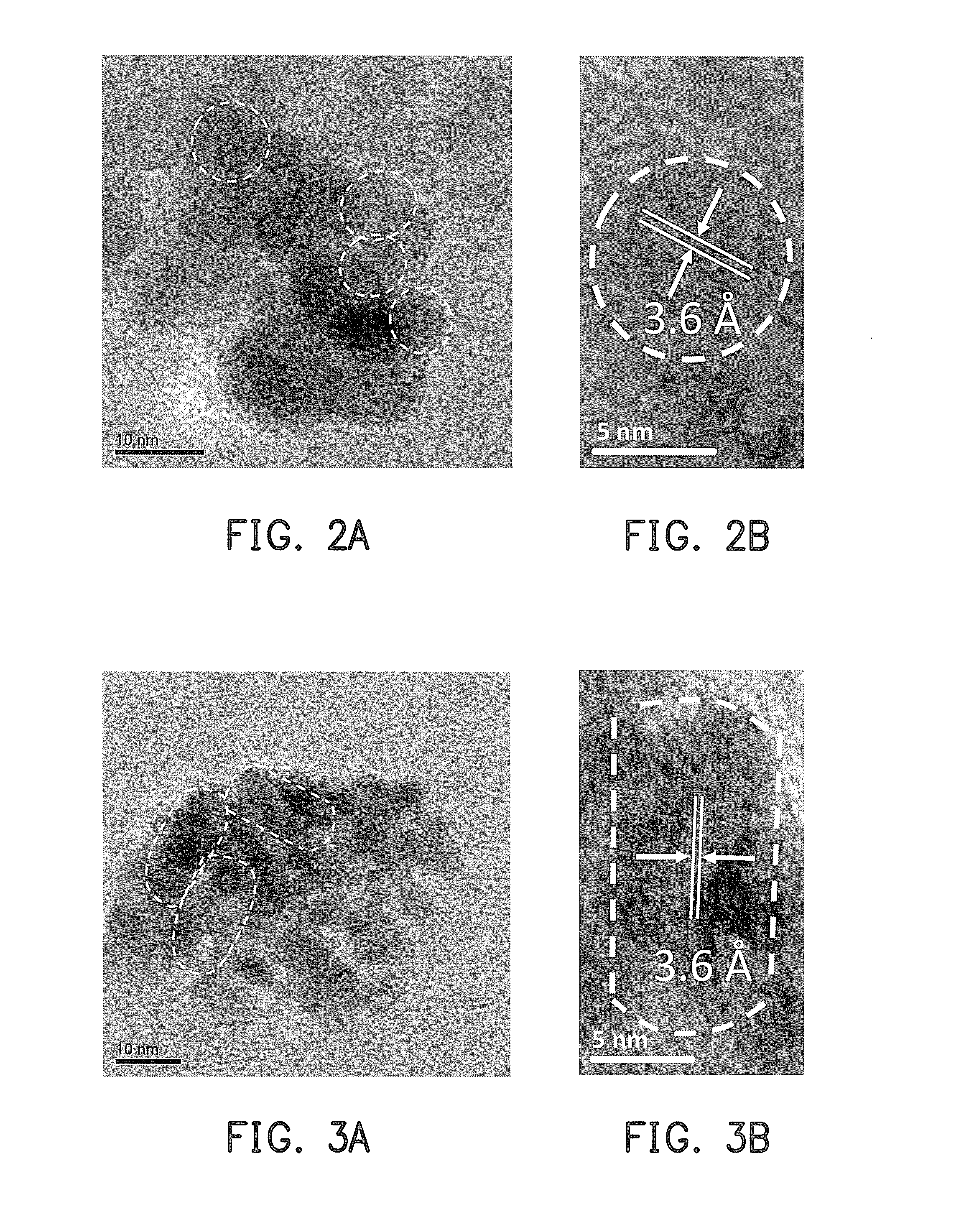
[0070]First, a graphene quantum dot powder was prepared with the same method as experimental example 1. Then, the graphene quantum dot powder of experimental example 1 was placed in a lidless quartz crucible and calcinated with a high-temperature calcination furnace at 300° C. for 10 minutes. After being cooled at room temperature, the graphene quantum dot powder of experimental example 2 was obtained. An analysis with an energy-dispersive spectroscope shows that the powder has the elements of carbon, oxygen, nitrogen, and silicon. Green light (525 nm to 550 nm) was emitted by the powder upon irradiation of an ultraviolet lamp (360 nm to 380 nm), and the particle size thereof was verified to be 13.2±0.8 nm (as shown in FIG. 3A) by HR-TEM. FIG. 3B is a partial enlarged diagram of an HR-TEM micrograph of the graphene quantum dot powder of experimental example 2. In FIG. 3A and FIG. 3B, the portion labeled with a white dashed frame is the atomi...
experimental example 3
Fabrication of Graphene Quantum Dot Powder
[0071]First, a graphene quantum dot powder was prepared with the same method as experimental example 1. Then, the graphene quantum dot powder of experimental example 1 was placed in a lidless quartz crucible and calcinated with a high-temperature calcination furnace at 300° C. for 20 minutes. After being cooled at room temperature, the graphene quantum dot powder of experimental example 3 was obtained. An analysis with an energy-dispersive spectroscope shows that the powder has the elements of carbon, oxygen, nitrogen, and silicon. Yellow light (570 nm to 590 nm) was emitted by the powder upon irradiation of an ultraviolet lamp (360 nm to 380 nm), and the particle size thereof was verified to be 28+3 nm (as shown in FIG. 4A) by HR-TEM. FIG. 4B is a partial enlarged diagram of an HR-TEM micrograph of the graphene quantum dot powder of experimental example 3. In FIG. 4A and FIG. 4B, the portion labeled with a white dashed frame is the atomic l...
PUM
| Property | Measurement | Unit |
|---|---|---|
| size | aaaaa | aaaaa |
| wavelength range | aaaaa | aaaaa |
| wavelength range | aaaaa | aaaaa |
Abstract
Description
Claims
Application Information
 - R&D
- Intellectual Property
- Life Sciences
- Materials
- Tech Scout
- Unparalleled Data Quality
- Higher Quality Content
- 60% Fewer Hallucinations
Browse by: Latest US Patents, China's latest patents, Technical Efficacy Thesaurus, Application Domain, Technology Topic, Popular Technical Reports.
© 2025 PatSnap. All rights reserved.Legal|Privacy policy|Modern Slavery Act Transparency Statement|Sitemap|About US| Contact US: help@patsnap.com