
Mesoporous inorganic coatings with photocatalytic particles in its pores

a technology of photocatalytic particles and pores, applied in the direction of anti-reflective coatings, physical/chemical process catalysts, instruments, etc., can solve the problems of affecting the application of broad-band anti-reflective coatings on low-index substrates, affecting the application of commercial products, and affecting the implementation of commercial products. achieve the effect of effective anti-reflective properties and effective self-cleaning properties

Inactive Publication Date: 2015-12-31
CAMBRIDGE ENTERPRISE LTD
View PDF3 Cites 6 Cited by
  • Summary
  • Abstract
  • Description
  • Claims
  • Application Information

AI Technical Summary

Benefits of technology

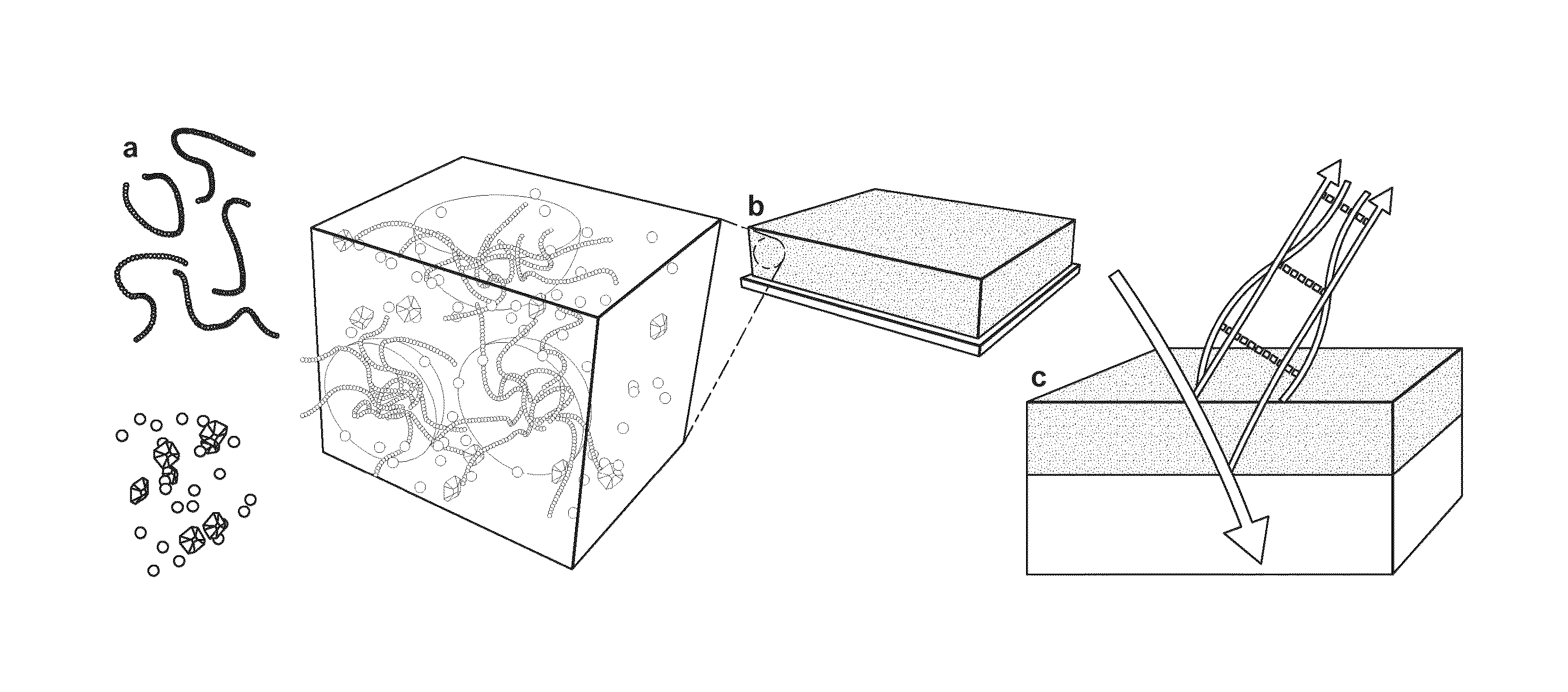
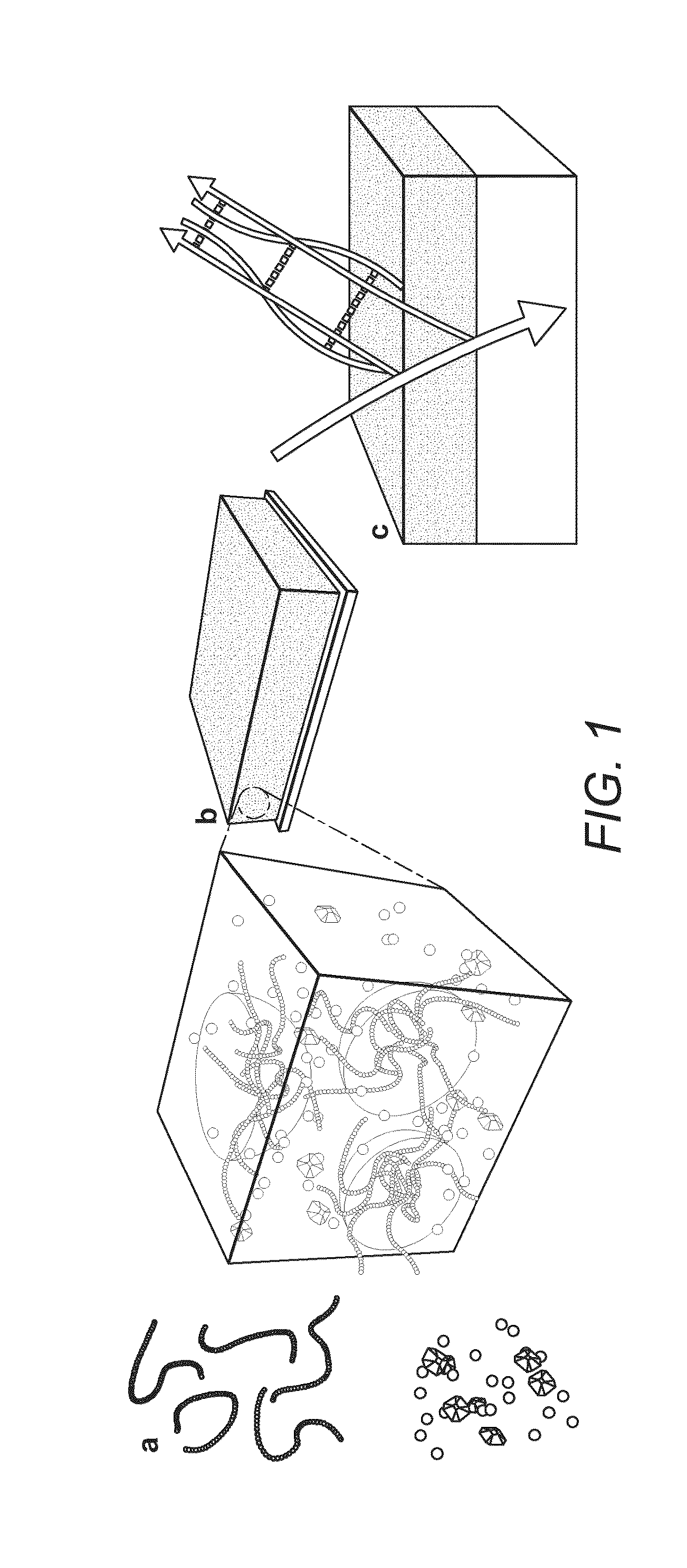
This patent describes a method of making a coating with photocatalytic properties using nanocrystals. By adding specific components to a mixture, the refractive index of the coating can be reduced. The method also allows for the distribution of photocatalytic particles throughout the structure, making them more effective and always available for use. The resulting coating has improved photocatalytic properties and can be easily applied to various materials.

Problems solved by technology

Whilst the physical requirements have long been understood, the implementation of broad-band anti reflective coatings on low index substrates remains a challenge.
While the first condition is easily met with modern deposition techniques, the second condition poses a challenge: many transparent materials have a refractive index around 1.5, requiring nar≈1.22.
Because of the lack of transparent optical materials with sufficiently low refractive index, this can only be achieved by the introduction of voids with sub-wavelength dimensions into the layer.
The effective refractive index of such material-air composites can be approximated by various effective medium theories2,3, such as the Bruggeman model Whilst research-grade nanostructured ARCs are close to perfection, their implementation in commercial products is hampered by their lack of wear resistance and optical variability caused by contamination of the nanostructure.
While photocatalytic self-cleaning is in principle more robust, the inclusion of a photocatalytic component in ARCs, typically TiO2, poses a major challenge because of the high refractive index of (nTiO2>(2.5).
Furthermore, the nanometre scale structure of the above-identified proposals limits the achievable porosity and thus the volume fraction of TiO2 that can be incorporated without compromising the required effective refractive index of the coating.

Method used


Image

  • Mesoporous inorganic coatings with photocatalytic particles in its pores
  • Mesoporous inorganic coatings with photocatalytic particles in its pores
  • Mesoporous inorganic coatings with photocatalytic particles in its pores

Examples


example 1

Variation of Porosity

Preparation of Block Co-Polymer

[0068]A high molecular weight block copolymer—poly(isoprene-block-ethylene oxide) (PI-b-PEO) was prepared according to the method of Allgaier et al8 and was dissolved in an azeotrope mixture of toluene and 1-butanol. 8 Allgaier, J., Poppe, A., Willner, L., and Richter, D. Macromolecules 30, 1582-1586 (1997).

Preparation of Silica-Based Sol

[0069]An aluminosilicate sol was prepared separately by the step-wise hydrolysis of a silicon / aluminium alkoxide mix (9 / 1 molar ratio), in which: 2.8 g (3-glycidyloxypropyl)trimethoxysilane (98%,Aldrich) and 0.32 g aluminum-tri-sec-butoxide (97%, Aldrich) were mixed with 20 mg KCl (TraceSELECT, Fluka) and promptly placed into an ice bath. In a first hydrolysis step, 0.135 ml of 10 mM HCl was added dropwise in 5 s intervals at 0° C. and stirred for 15 min. After warming to room temperature, 0.85 ml of 10 mM HCl was further added dropwise.

[0070]A first set of experiments were conducted to determine t...

example 2

Variation of Pore Size

[0079]Using the above methodology, it was possible to prepare coatings from solutions fabricated with polymers of different polymer weight content, as follows:

ExamplePolymerMn (kg mol−1)Wt % PEO2API-b-PEO3434.428.02BPI-b-PEO9291.631.5

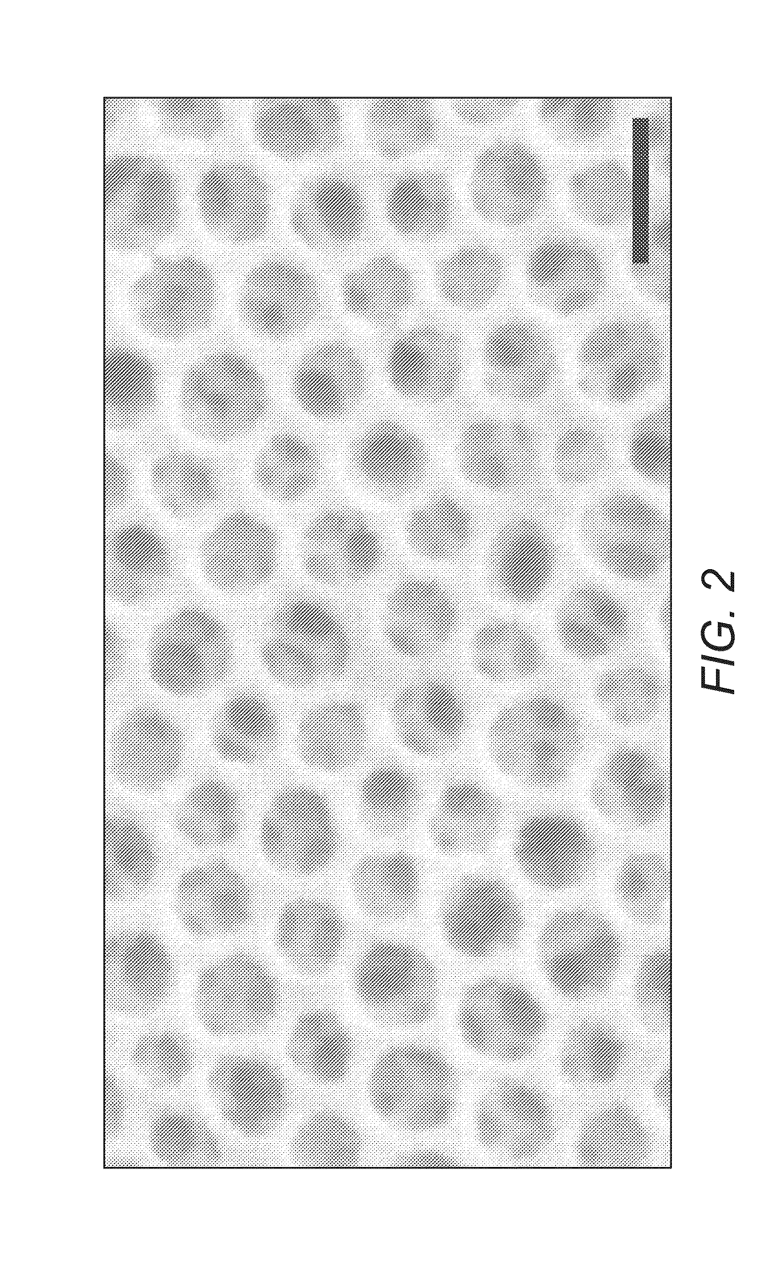
[0080]FIG. 2 shows the morphology of the film with similar inorganic loading as in Example 1 but with an increased PI molecular weight.

[0081]In this Example the copolymer had an increased PI chain length of 62.7 kg mol−1. The increase in chain length resulted in 53 nm-wide pores. This increase is in good agreement with scaling laws governing polymer chains in a good solvent. The radius of gyration of the pore forming PI block scales by a factor of 1.59 when increasing the molecular weight from 24.8 to 62.7 kg mol−1, which is consistent with the pore size determination by SEM image analysis.

example 3

Variation of Chemical Route to Porous Skeleton

[0082]In another experiment the materials route to the porous skeleton is altered. Most common pathways for the low refractive index inorganic components involve sol-gel chemistry with hydrolysis and condensation of the precursor chemicals. There are several non-hydrolytic alterations, where the precursor reaction takes place in an organic solvent under the exclusion of water.9 9 Sol-Gel Material: Chemistry and Applications, J. D. Wright, N. A. J. M. Sommerdijk, P. O'Brien, D. Phillips, CRC Press, 1st edition (2000)

[0083]Instead of following the standard routes of hydrolytic or non-hydrolytic sol-gel chemistry, an alternative precursor material is used, namely poly(methyl silsesquioxane) (PMSSQ) copolymer.10 In this case the PMSSQ copolymer is dissolved in 1-butanol, mixed with the block copolymer solution. The further processing (annealing and etching) then follows the route explained in Example 1. 10 S. Kim, J. Cho, K. Char, Langmuir, ...


PUM

PropertyMeasurementUnit
Fractionaaaaaaaaaa
Fractionaaaaaaaaaa
Fractionaaaaaaaaaa

Abstract

This invention relates to coatings for substrates, in particular antireflective coatings (ARCs) and self-cleaning coatings (SCCs). A coating for a substrate comprises a mesoporous inorganic skeleton having photocatalytic particles provided therein and / or thereon, the coating having a porosity in excess of 50 v / v %, for example, greater than 55%, 60%, 65%, 70 v / v %.

Description

CROSS-REFERENCE TO RELATED APPLICATIONS[0001]This application is a continuation of and claims the benefit of priority of International Application No. PCT / GB2013 / 051841, filed Jul. 11, 2013, which in turn claims the benefit of priority to GB application number 1212361.8, filed Jul. 11, 2012.BACKGROUND[0002]1. Field of the Disclosure[0003]This invention relates to coatings for substrates, in particular antireflective coatings (ARCs) and self-cleaning coatings (SCCs). The invention is particularly concerned with a coating which is both an ARC and an SCC, which we term a self-cleaning antireflective coating (SCARC).[0004]2. Description of Related Art[0005]Since the first experimental approaches to the reduction of light reflection from optical interfaces, works have sought to continuously optimize the performance of antireflection coatings. Whilst the physical requirements have long been understood, the implementation of broad-band anti reflective coatings on low index substrates remai...

Claims


Application Information

Patent Timeline
IPC IPC(8): C09D153/00G02B1/18B05D5/08G02B1/111C09D5/00B05D1/00C08J7/056
CPCC03C17/007C03C17/009C03C2217/425C03C2217/452C03C2217/477C03C2217/48C03C2217/71C03C2217/732C03C1/008G02B1/113G02B2207/107C08J7/045C08J2383/04G02B27/0006B01J37/0219B01J21/063B01J35/0013B01J35/002B01J35/004B01J35/1057B01J35/1061B01J35/1066B01J37/0018B01J37/0215G02B1/18B05D1/005B05D5/08C09D5/006C09D153/00G02B1/111C08J7/056B01J35/39B01J35/30B01J35/23B01J35/643B01J35/647B01J35/651C08J7/0423
Inventor GULDIN, STEFANSTEINER, ULLRICH
Owner CAMBRIDGE ENTERPRISE LTD
Learn More