Method for producing phosphor
a phosphor and phosphor technology, applied in the field of phosphor production, can solve the problems of loss of color reproducibility and inferior color rendering properties for illumination applications, and achieve the effect of improving the yield of production and high fluorescence peak intensity
- Summary
- Abstract
- Description
- Claims
- Application Information
AI Technical Summary
Benefits of technology
Problems solved by technology
Method used
Image

Examples
example 1
[0040]Metal strontium (38-0074 grade, purity: 99.9%, produced by Strem Chemicals Inc.) was placed in an alumina boat in a glove box under nitrogen-substituted atmosphere; the alumina boat was placed in a quartz pipe; both ends of the quartz pipe were sealed; and the quartz pipe having the metal strontium therein was withdrawn from the glove box. The quartz pipe was placed in a solenoidal furnace; nitrogen gas pipes were connected to the quartz pipe; and the quartz pipe and the nitrogen gas lines were evacuated under vacuum.
[0041]Nitrogen gas was introduced into the quartz pipe; metal strontium was heated to 600° C. under nitrogen flow and held at the same temperature for 3 hours, heated to 850° C. and held at the same temperature for 1 hours, and cooled. Both ends of the quartz pipe were sealed, the strontium nitride obtained was collected in a glove box, and the product was screened with a sieve having an opening of 290 μm, to give the strontium nitride desired.
[0042]The strontium ...
example 2
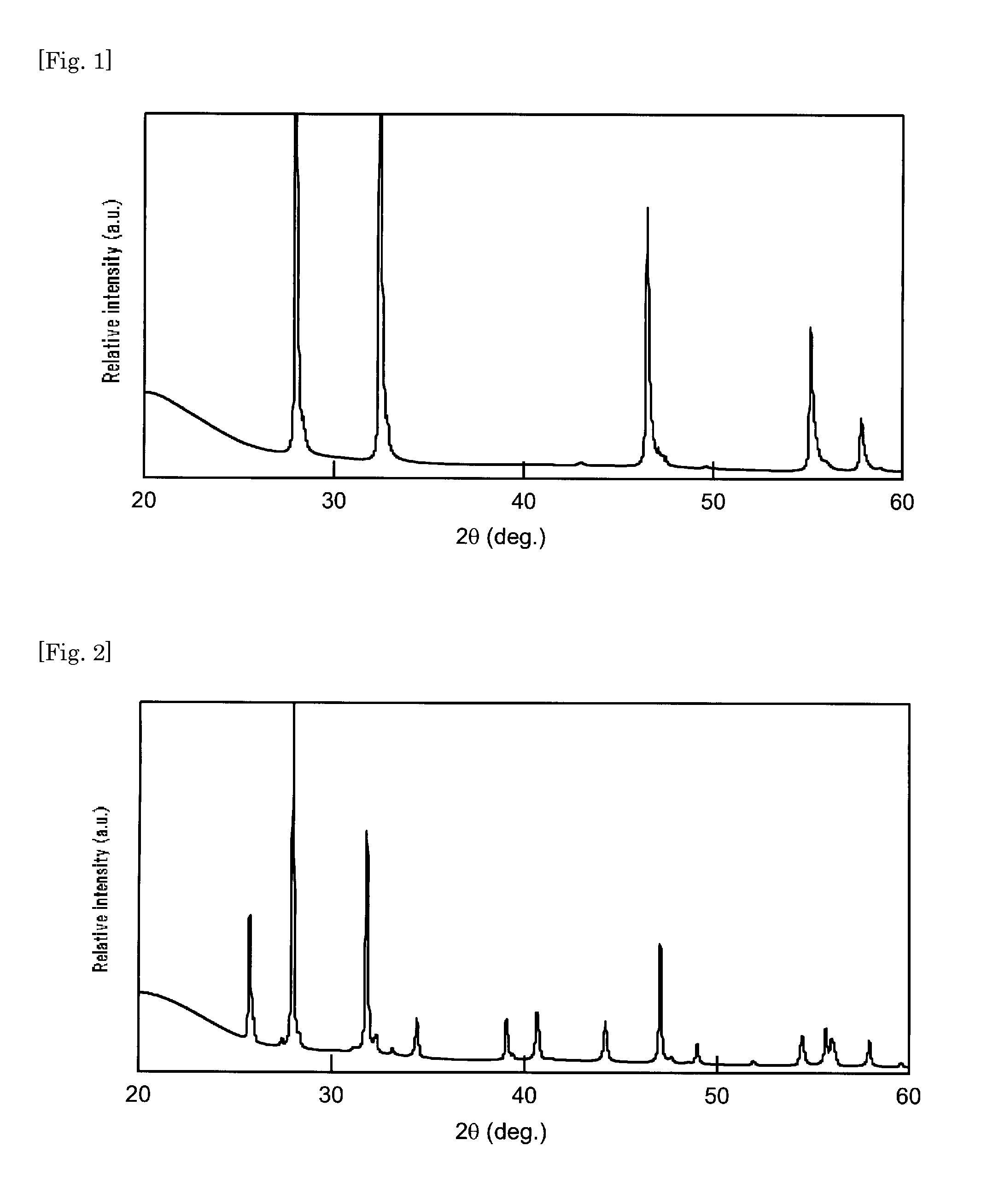
[0052]A phosphor was prepared using a strontium nitride powder obtained by a method similar to that in Example 1, except that, under the condition of nitriding the metal strontium in Example 1, the metal strontium was heated to about 600° C. under nitrogen flow and held at the same temperature for about 3 hours and cooled without the step of heating it to 850° C. The X-ray diffraction pattern of the strontium nitride used in Example 2 is shown in FIG. 2. The X-ray diffraction pattern shown in FIG. 2 was compared with that on the JCPDS card, showing that the crystalline phase thereof was identical with that of Sr2N crystalline phase.
[0053]The phosphor of Example 2 had a nitrogen content of strontium nitride smaller than that of Example 1, but the fluorescence peak intensity of the phosphor obtained was mostly equivalent to that of Example 1 and contamination of heterogeneous phase components was also smaller.
example 3
[0054]A phosphor was prepared by a method similar to that in Example 1, using a mixed powder of SrN and Sr2N crystalline phases obtained by mixing the strontium nitride used in Example 1 and the strontium nitride used in Example 2 in the same amount. The phosphor of Example 3 had a fluorescence peak intensity mostly equivalent to that of Example 1 and contamination of the heterogeneous phase components was also smaller.
PUM
 Abstract
Description
Claims
Application Information
 - R&D
- Intellectual Property
- Life Sciences
- Materials
- Tech Scout
- Unparalleled Data Quality
- Higher Quality Content
- 60% Fewer Hallucinations
Browse by: Latest US Patents, China's latest patents, Technical Efficacy Thesaurus, Application Domain, Technology Topic, Popular Technical Reports.
© 2025 PatSnap. All rights reserved.Legal|Privacy policy|Modern Slavery Act Transparency Statement|Sitemap|About US| Contact US: help@patsnap.com