
Aluminum electric wire with crimp-type terminal and method of manufacturing the same

a technology of aluminum electric wire and crimp terminal, which is applied in the direction of insulated conductors, cable terminations, cables, etc., can solve the problems of increasing manufacturing costs and progressing galvanic corrosion, and achieve the effect of reducing the progression rate of galvanic corrosion and convenient operation

Inactive Publication Date: 2015-10-08
YAZAKI CORP
View PDF7 Cites 29 Cited by
  • Summary
  • Abstract
  • Description
  • Claims
  • Application Information

AI Technical Summary

Benefits of technology

This patent is about an aluminum electric wire with a crimp-type terminal and a method of manufacturing it. The invention aims to slow down the rate of corrosion at the contact point between the crimp-type terminal and the conductor. The method involves integrating multiple element wires made of aluminum or aluminum alloy and crimping them to the terminal made of copper or copper alloy to decrease the area ratio of the cathode portion to the anode portion and slow down the corrosion. A water-repellent agent is also applied to the exposed conductor portions to prevent moisture attachment and minimize the contact area with water, further retarding corrosion. The method ensures easy and cost-effective manufacturing without compromising conductivity.

Problems solved by technology

However, when the conductor of an electric wire and the crimp-type terminal are dissimilar metals, contact of moisture to a contact portion of both metals causes galvanic corrosion to progress because the metal being an anode portion dissolves into water as ions.
However, though an above-described conventional coupled structure 501 is constituted by covering a wire coupling portion 511 by use of an insulator 515, and preventing the moisture from penetrating into the wire coupling portion 511, a thickness control for the insulator 515 is required for prevention of moisture penetration and causes an increase of manufacturing cost.

Method used


Image

  • Aluminum electric wire with crimp-type terminal and method of manufacturing the same
  • Aluminum electric wire with crimp-type terminal and method of manufacturing the same
  • Aluminum electric wire with crimp-type terminal and method of manufacturing the same

Examples


Embodiment Construction

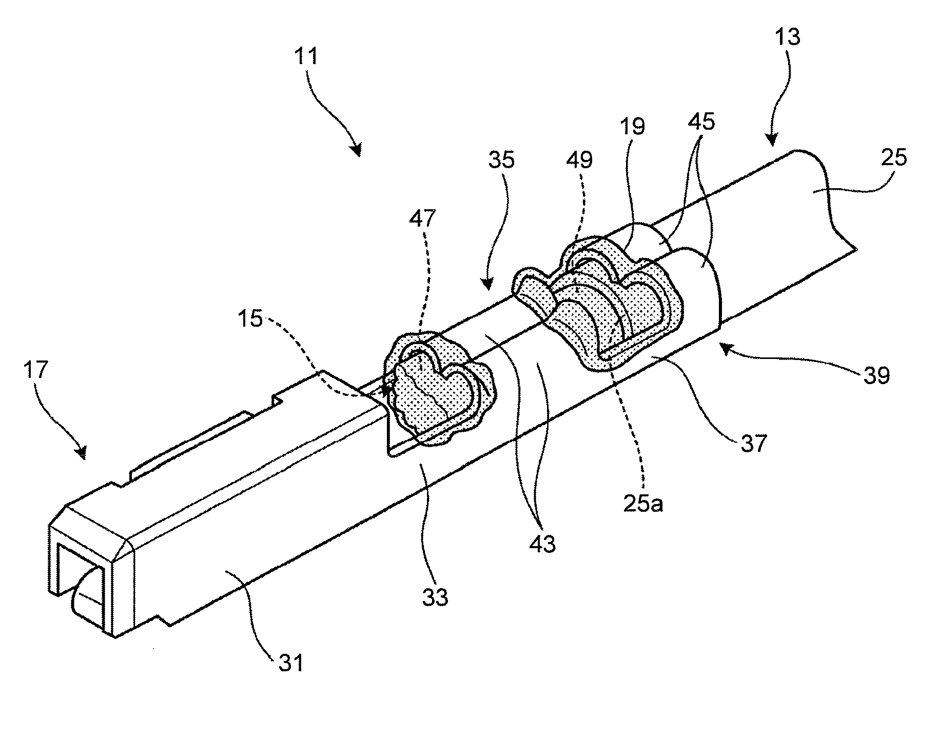
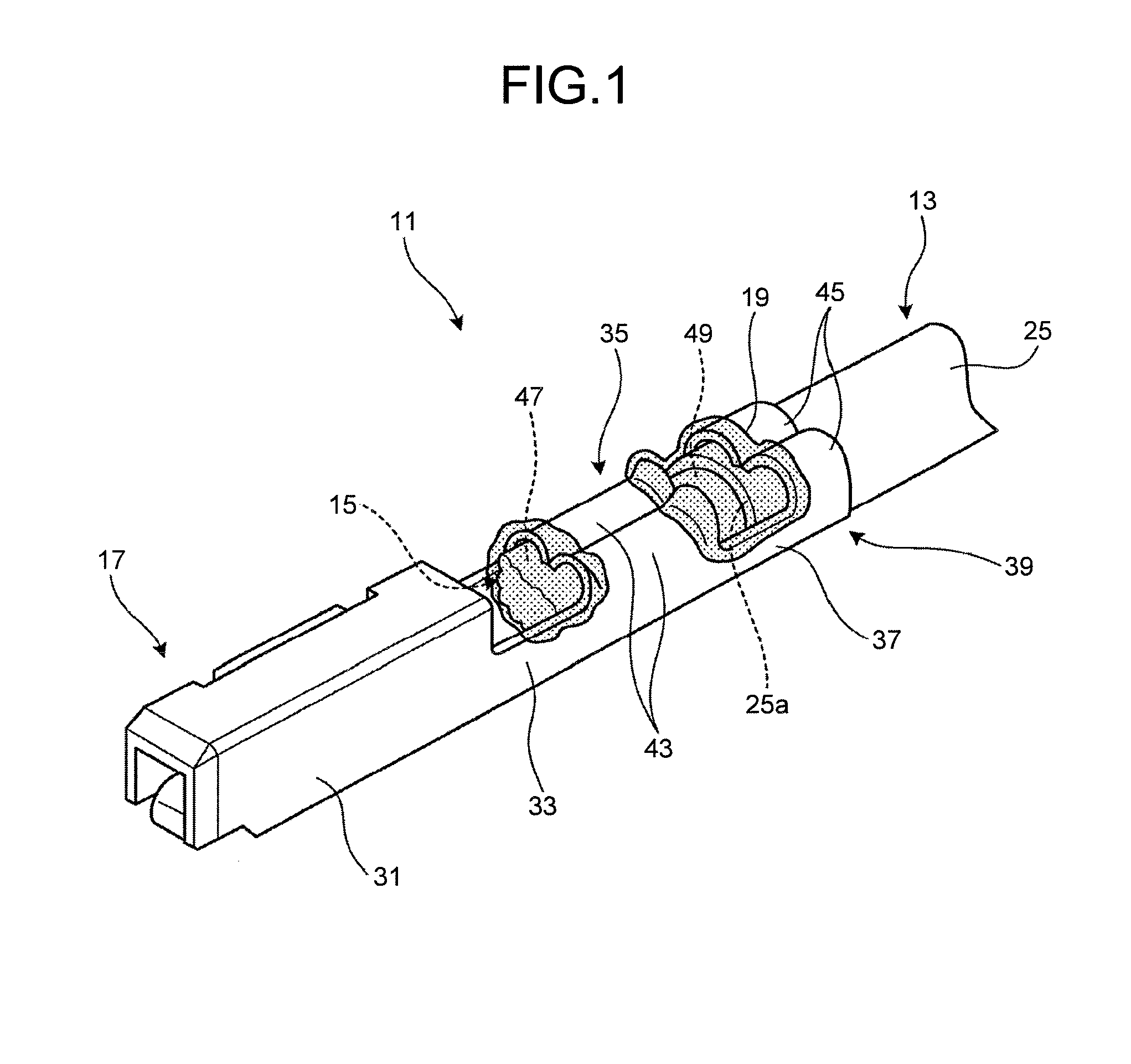
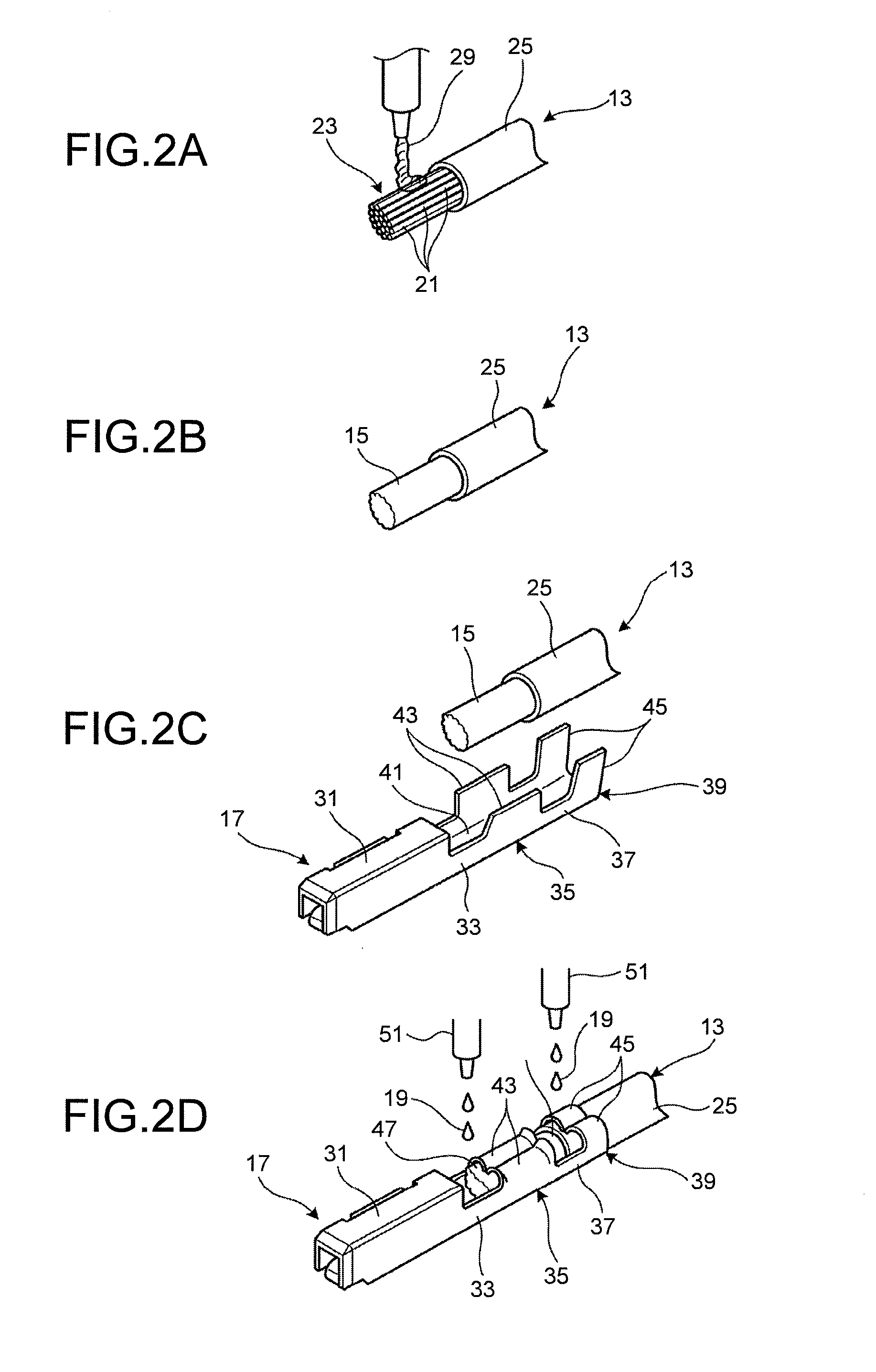
[0030]The following describes an embodiment according to the present invention with reference to drawings. As illustrated in FIG. 1, an aluminum electric wire with crimp-type terminal 11 according to one embodiment of the present invention is mainly constituted from a coated electric wire 13, a conductor portion 15 where a plurality of aluminum element wires (element wire) 21 of the coated electric wire 13 is integrally formed into a solid wire, a crimp-type terminal 17, and a water-repellent agent 19.

[0031]The coated electric wire 13 has a conductor 23 where the aluminum element wires 21 being the plurality of element wires made of aluminum or the aluminum alloy are twisted, and the conductor 23 is covered by an insulating coating 25 being an insulator made of an insulating resin (see FIG. 4A). A distal end side of the coated electric wire 13, which is an end where the crimp-type terminal 17 is coupled, becomes an electric wire distal end portion 27 where the conductor 23 is expose...


PUM

PropertyMeasurementUnit
contact angleaaaaaaaaaa
weightaaaaaaaaaa

Abstract

An aluminum electric wire with crimp-type terminal includes a coated electric wire including a conductor having a plurality of twisted aluminum element wires made of an aluminum alloy, a conductor portion where the plurality of aluminum element wires exposed by stripping an insulating coating of the coated electric wire are integrally formed into a solid wire, a crimp-type terminal made of a copper alloy having a conductor crimping portion crimped to couple to the conductor portion formed into the solid wire, and a water-repellent agent provided for a front side exposed conductor portion and a rear side exposed conductor portion 49 exposed to outside air without being covered by the conductor crimping portion of the crimp-type terminal.

Description

CROSS-REFERENCE TO RELATED APPLICATION[0001]This application is a continuation application of International Application PCT / JP2013 / 084571, filed on Dec. 25, 2013, and designating the U.S., the entire contents of which are incorporated herein by reference.BACKGROUND OF THE INVENTION[0002]1. Field of the Invention[0003]The present invention relates to an aluminum electric wire with crimp-type terminal and a method of manufacturing the same.[0004]2. Description of the Related Art[0005]Recently, in a field of a wire harness wired in a vehicle such as an automobile, an aluminum electric wire aimed at weight reduction or similar effect is noted instead of a copper electric wire. The aluminum electric wire is constituted from a conductor formed from stranded wires with a plurality of twisted aluminum element wires, and covered by an insulating coating. For manufacturing a wire harness with the aluminum electric wire, a crimp-type terminal is coupled to its end. However, when the conductor ...

Claims


Application Information

Patent Timeline
Patent Type & Authority Applications(United States)
IPC IPC(8): H01B7/282H01B5/12H01R43/05H01R4/18H01R43/00H01B1/02H01B7/00
CPCY10T29/49192H01B7/282H01B1/02H01R43/05H01B7/00H01R4/18H01R43/005H01B5/12H01R4/185H01R4/625H01R4/70H01R43/048H01B1/023H01B7/28H01R4/62
Inventor SATO, KEI
Owner YAZAKI CORP
Learn More