Method for preparing carbon nanofiber composite and carbon nanofiber composite prepared thereby
a carbon nanofiber composite and carbon nanofiber composite technology, applied in the field of carbon nanofiber composite and carbon nanofiber composite prepared thereby, can solve the problems of not being commercialized and exhibiting photocatalytic activity, and achieve the effects of improving yield, improving preparation process efficiency, and improving decomposition ra
- Summary
- Abstract
- Description
- Claims
- Application Information
AI Technical Summary
Benefits of technology
Problems solved by technology
Method used
Image
Examples
example 1
[0063]10 wt % of a material of a carbon fiber precursor of PAN was dissolved in a DMF solvent to prepare a PAN solution. To the PAN solution, a titanium dioxide (TiO2) powder with a nanosize prepared by a sol-gel method was added to prepare a PAN dispersion containing the titanium dioxide. The amount of the titanium dioxide (TiO2) powder was 10 wt %. The dispersion was mechanically stirred for 4 hours to disperse the titanium dioxide (TiO2) in the dispersion well and to mix completely.
[0064]The PAN dispersion including the titanium dioxide (TiO2) was electrospinned in an electric field of 20 kV to prepare a carbon nanofiber containing the titanium dioxide (TiO2).
[0065]After heating the carbon nanofiber in an oxygen atmosphere at 250° C. for 30 minutes, the temperature was firstly elevated to 750° C. with a temperature elevation rate of 5° C. / min under a nitrogen gas, heating was performed while maintaining the temperature of 750° C. for 1 hour, the temperature was secondly elevated ...
experimental example 1
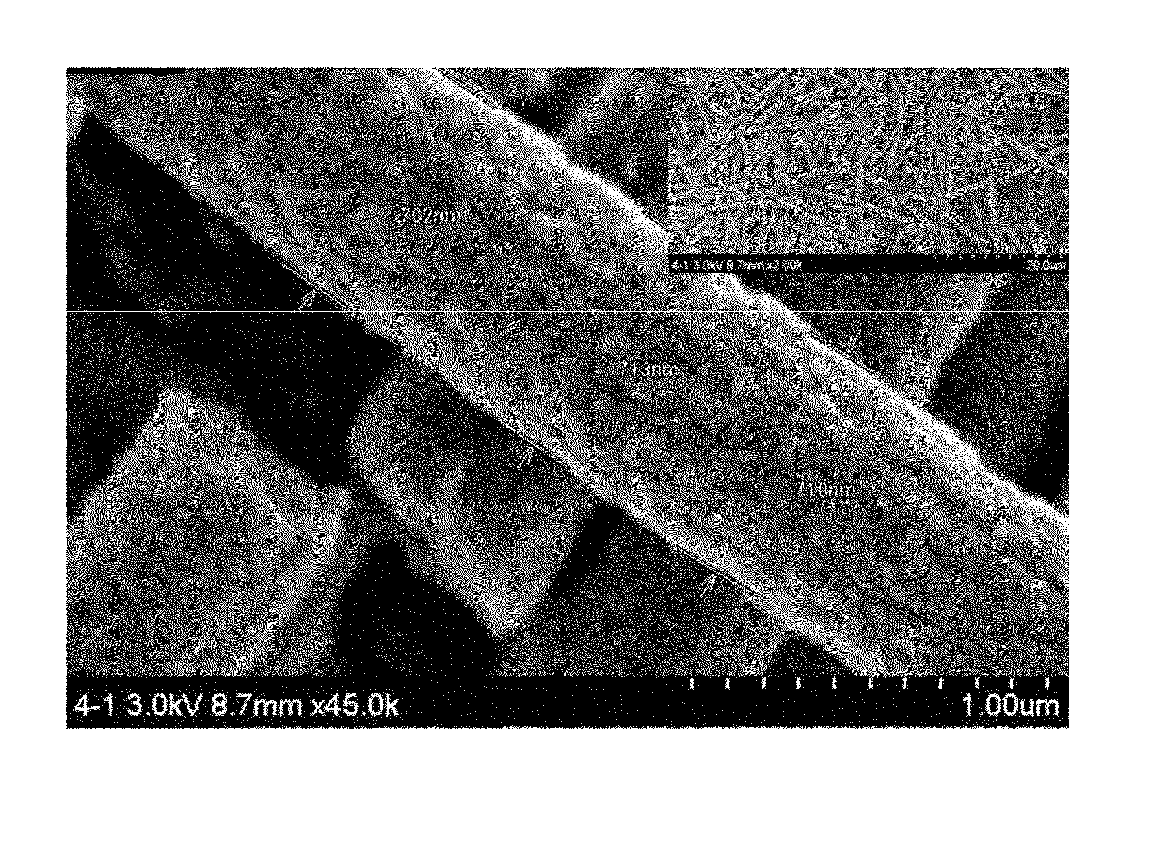
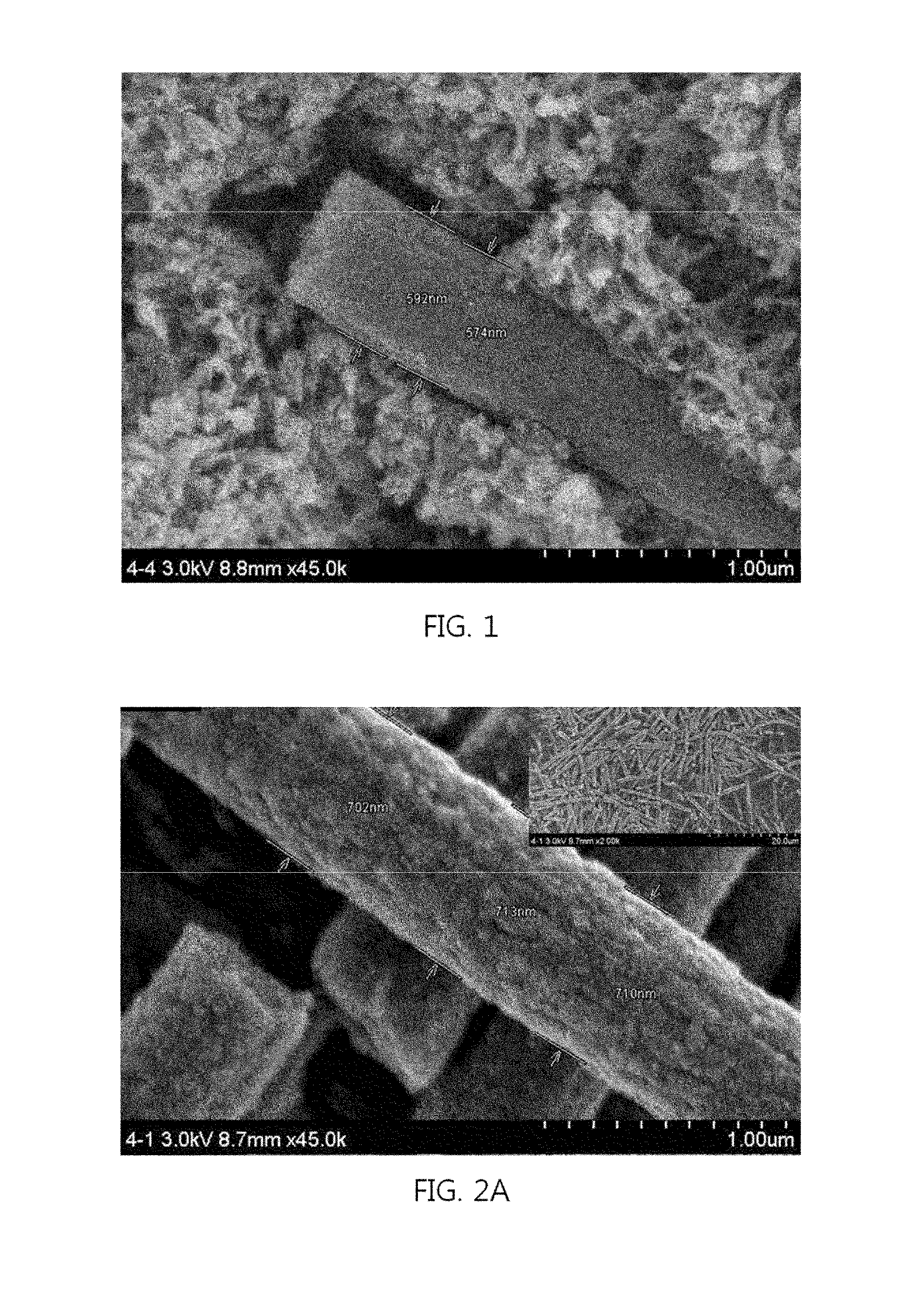
[0069]The carbon nanofiber composites prepared in Example 1 and Comparative Examples 1 to 3 were identified by taking an image with a scanning electron microscope (Hitachi S-4200 FE-SEM), and the results will be explained referring to FIG. 1 and FIGS. 2A to 2D.
[0070]FIG. 1 is a scanning electronic microscopic image of a carbon nanofiber composite prepared in Example 1, and a shape of wrapping the surface of a carbon nanofiber having an average diameter of 600 nm with a plurality of titanate nanotubes with an outer average diameter of 20 nm and an inner average diameter of 10 nm may be observed.
[0071]FIG. 2A corresponds to a scanning electronic microscopic image according to Comparative Examples 1, FIG. 2B corresponds to Comparative Example 2, FIG. 2C corresponds to Comparative Example 3 and FIG. 2D corresponds to Example 1. From Example 1 and Comparative Example 3, the production of the plurality of titanate nanotubes according to the hydrothermal treatment could be clearly secured,...
experimental example 2
[0072]X-ray diffraction of the carbon nanofiber composite prepared in Example 1 and Comparative Examples 1 to 3 was taken (Rigaku D / MAX-2500, 18 kV) and secured. The results will be explained referring to FIGS. 3A and 3B.
[0073]As shown in FIGS. 3A and 3B, the carbon nanofiber according to Comparative Example 1 was found that titanium dioxide was reduced to have a crystalline structure of titanium nitride (TiN). Through Comparative Example 2, it could be found that the phase of a portion of the titanium dioxide was changed to titanium dioxide with an anatase crystalline phase. The crystalline phase of the titanium nitride was completely changed in Example 1, and was hardly shown in the structure of a carbon nanofiber composite. In addition, when comparing Comparative Example 3 with Example 1, it may be secured that only the crystalline phase of titanate could be observed, and the phase of a portion of the titanium dioxide with the anatase crystalline phase was changed according to th...
PUM
| Property | Measurement | Unit |
|---|---|---|
| Temperature | aaaaa | aaaaa |
| Temperature | aaaaa | aaaaa |
| Temperature | aaaaa | aaaaa |
Abstract
Description
Claims
Application Information
 - R&D
- Intellectual Property
- Life Sciences
- Materials
- Tech Scout
- Unparalleled Data Quality
- Higher Quality Content
- 60% Fewer Hallucinations
Browse by: Latest US Patents, China's latest patents, Technical Efficacy Thesaurus, Application Domain, Technology Topic, Popular Technical Reports.
© 2025 PatSnap. All rights reserved.Legal|Privacy policy|Modern Slavery Act Transparency Statement|Sitemap|About US| Contact US: help@patsnap.com


