
Plated terminal for connector and terminal pair

a technology of plated terminals and connectors, applied in the direction of coupling contact members, coupling device connections, electrical devices, etc., can solve the problems of high friction coefficient, difficult connection operation, and large insertion force, so as to suppress the insertion force of the terminal, reduce the friction coefficient of the surface, and high hardness

Active Publication Date: 2015-05-14
AUTONETWORKS TECH LTD +2
View PDF2 Cites 19 Cited by
  • Summary
  • Abstract
  • Description
  • Claims
  • Application Information

AI Technical Summary

Benefits of technology

The invention is about a new connector terminal that has a layer made of tin-palladium alloy on its surface. This layer has high hardness and reduces friction between the terminals, which results in a lower force required to insert the terminals and a better electrical connection. The friction reduction is achieved by having a high exposure ratio of the first metal phase, which is made of tin and palladium. The second metal phase, which is pure tin or a tin-palladium alloy with a higher ratio of tin to palladium, ensures a good electrical contact. The terminals can be connected even if there is no oxide film formed on the surface, as long as the contact load is not too high. The invention thus provides a solution for reducing friction and improving the connection between terminals.

Problems solved by technology

However, since the tin oxide film is destroyed with a weak force and the soft tin layer is easily exposed, good electrical contact is established.
In the connector terminal formed with the tin plating layer, good electrical contact can be established as described above due to the softness of tin, whereas there is a problem of a high friction coefficient at the time of terminal connection likewise due to the softness of tin.
Particularly, in the case of using tin plating for terminals of a multi-pole fitting connector including many terminals, the insertion force becomes larger as the number of the terminals increases and a connecting operation becomes difficult.

Method used


Image

  • Plated terminal for connector and terminal pair
  • Plated terminal for connector and terminal pair
  • Plated terminal for connector and terminal pair

Examples


example 1

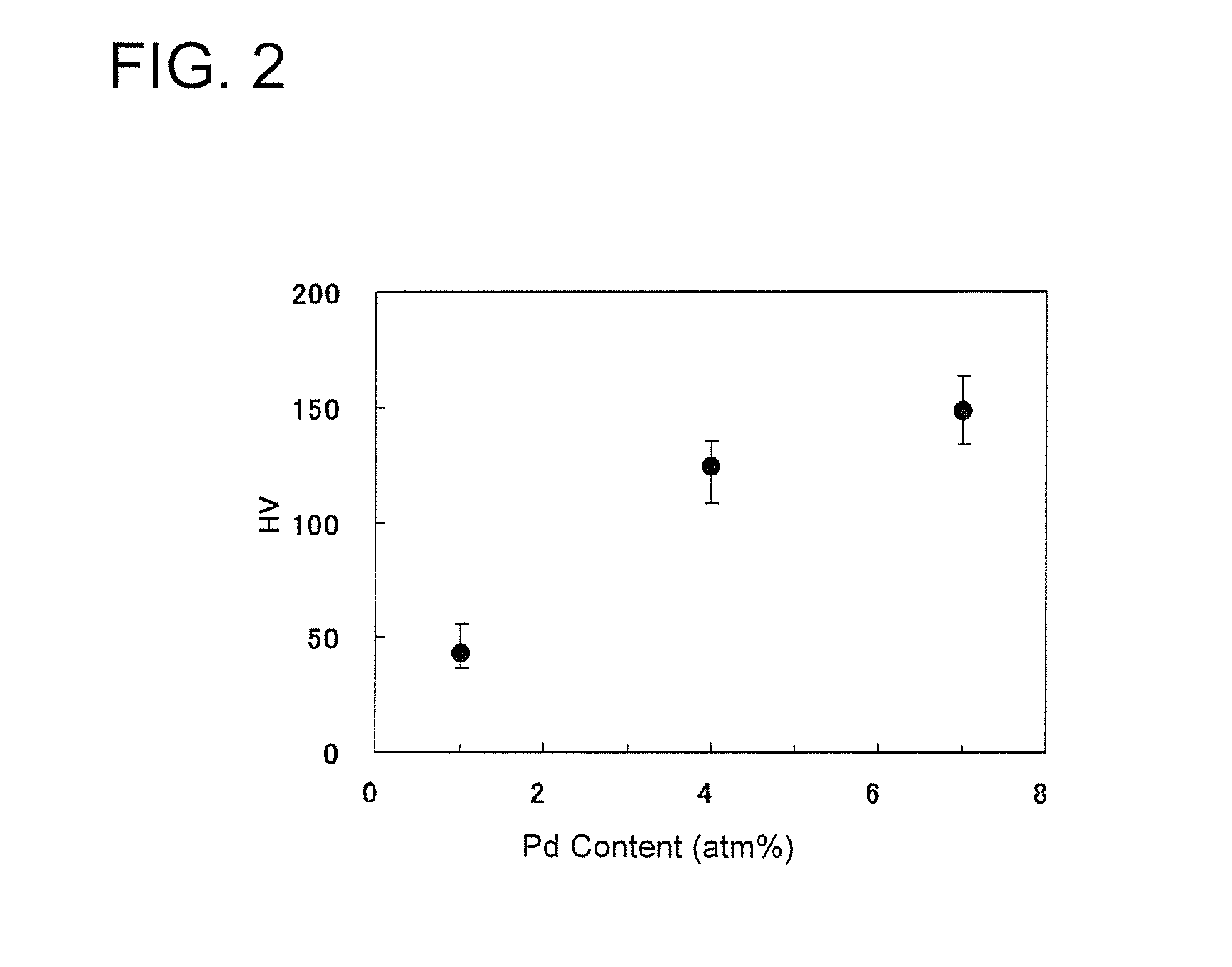
Evaluation of Hardness and Friction Coefficient of Tin-Palladium Alloy Containing Layer

[0060](Fabrication of Samples)

[0061]A nickel under plating layer having a thickness of 1 μm was formed on a clean surface of a copper board and a palladium plating layer was formed on the nickel under plating layer. Subsequently, a tin plating layer was formed on the palladium plating layer. This was heated at 280° C. in the atmosphere, thereby forming a tin-palladium alloy containing layer and a plated member according to the example.

[0062]Here, the content of palladium in the tin-palladium alloy containing layer was specified by adjusting thicknesses of the tin plating layer and the palladium plating layer. Specifically, tin-palladium alloy containing layers having a palladium content of 1 atom %, 4 atom % and 7 atom % were formed by setting the thickness of the tin plating layer at 2 μm and setting the thickness of the palladium plating layer at 0.02 μm, 0.05 μm and 0.09 μm. Note that the conte...

example 3

Evaluation of Contact Resistance Increase Caused by Heating

[0097]To estimate a degree of an increase in the contact resistance value associated with use under a heating environment, a degree of a contact resistance increase caused by heating was evaluated using the same samples used in Example 1. That is, contact resistance was measured by a four-terminal method under the same conditions as in the contact resistance measurement in Example 2 for each plated member in an initial state (immediately after fabrication). Subsequently, each plated member was left at 160° C. in the atmosphere for 120 hours (hereinafter, this condition may be referred to as “left at high temperature”). After the samples left at high temperature were cooled to room temperature, contact resistance was similarly measured. Focusing on a contact resistance value at a load of 10 N, a value increased from the initial state to the state left at high temperature was set as a resistance increase value.

[0098]TABLE-2 sh...

example 4

Evaluation of Relationship Between Contact Portion Shape and Friction Coefficient

[0100]The friction coefficient is affected not only by the configuration of the metal layer on the surface of the contact portion, but also by the shape of the contact portion constituting the terminal pair. Thus, the friction coefficient was measured while the contact portion shape was varied to estimate which shape of the contact portion of the terminal pair leads to an increase in the effect of reducing the friction coefficient by the tin-palladium alloy containing layer. That is, a male connector terminal including a flat plate-like terminal tab and a female connector terminal including an emboss-like contact portion were respectively formed using plated members with a Pd content of 1 atom %, 4 atom % and 7 atom % and a tin plated member formed as in Example 1. Then, the friction coefficient was measured as in the case of Example 1 for a case where both the male and female connector terminals were f...


PUM

PropertyMeasurementUnit
Fractionaaaaaaaaaa
Fractionaaaaaaaaaa
Fractionaaaaaaaaaa

Abstract

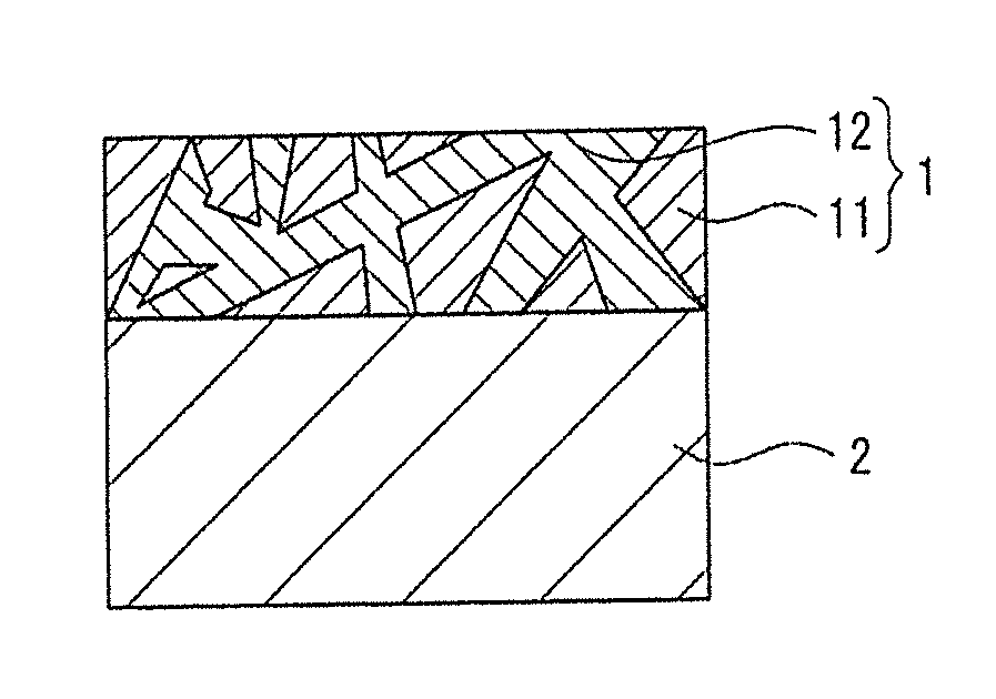
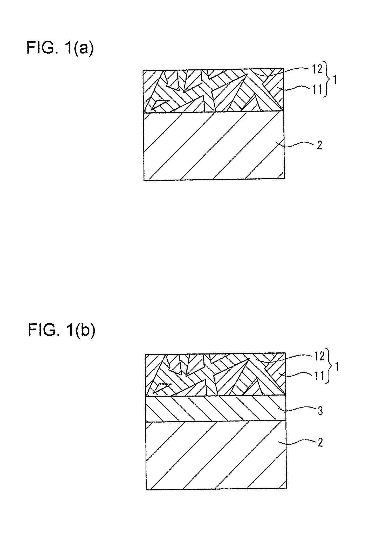
The present invention aims to provide a plated terminal for connector which requires a smaller insertion force by reducing a friction coefficient and a terminal pair formed using such a plated terminal for connector. An alloy containing layer (1) made of tin and palladium and containing a tin-palladium alloy is formed on a surface of a terminal base material (2) made of copper or copper alloy. Here, the alloy containing layer (1) is preferably such that domain structures of a first metal phase (11) made of an alloy of tin and palladium are formed in a second metal phase (12) made of pure tin or an alloy having a higher ratio of tin to palladium than in the first metal phase (11).

Description

BACKGROUND OF THE INVENTION[0001]1. Field of the Invention[0002]The present invention relates to a plated terminal for connector, more particularly to a plated terminal for connector including an alloy plating layer, and a terminal pair formed by using such a plated terminal.[0003]2. Description of the Related Art[0004]Copper and copper alloy having high electrical conductivity, good ductility and appropriate strength are used for electrically conductive members used such as in electrical connection terminals. Since insulating films such as oxide films and sulfide films are formed on surfaces of these, contact resistance is high at the time of contact with other conductors. Accordingly, a terminal formed by applying tin plating 21 to a surface of a base material 22 such as copper or copper alloy as shown in FIG. 7(b) has been conventionally generally used as a connector terminal for connecting an electrical component or the like of an automotive vehicle. For example, a connector ter...

Claims


Application Information

Patent Timeline
IPC IPC(8): H01R13/03
CPCH01R13/03C25D3/60C25D5/12C25D7/00C25D5/627
Inventor SAKA, YOSHIFUMIWATANABE, HAJIMESATOU, MIKIOOOKUBO, MASAYUKI
Owner AUTONETWORKS TECH LTD
Learn More