
Metal-air flow batteries using oxygen enriched electrolyte

Active Publication Date: 2015-05-07
FLORIDA STATE UNIV RES FOUND INC
View PDF4 Cites 13 Cited by
  • Summary
  • Abstract
  • Description
  • Claims
  • Application Information

AI Technical Summary

Benefits of technology

The patent describes a special membrane that allows for good conductivity of lithium ions and is stable in both non-aqueous and aqueous solutions. The membrane is also able to separate two electrolytes. This membrane is called Celgard 2400. The technical effect of this patent is the ability to create an efficient and stable system for conducting electricity using lithium ions.

Problems solved by technology

Due to the variable and stochastic nature of renewable sources this energy is difficult to manage, especially at high levels of penetration.
The current lead-acid and flow batteries that are being used in grid-connected renewable systems are not cost effective and reliable enough to be integrated in large grids.
Although traditional Li-air batteries have an extremely large theoretical energy density, they suffer from several drawbacks: (1) the Li2O2 / Li2O discharge product deposits on the air side of the electrode reducing the pore size and limiting the access of O2 into the cathode.
This inhomogenous deposition of reaction products severely limits the usage of cathode volume, which limits the maximum capacity and energy density of the battery; (2) the cyclability and energy efficiency of Li-air batteries are poor due to the lack of effective catalysts to convert solid Li2O2 / Li2O discharge products into Li ions; and (3) the current and power densities of Li-air batteries are much lower compared to conventional batteries due to the extremely low oxygen diffusion coefficient in liquid solution.
The poor reversibility of Li-air batteries is due to the formation of solid oxide discharge products which are difficult to reduce and decompose into Li-ions and oxygen within the electrolyte's stable potential.
Improved catalysts could reduce the reduction potential but could not effectively reduce all solid oxide products deposited in a highly porous electrode.
The most significant challenge to rechargeability of Li-air batteries is the formation of solid discharge products.

Method used


Image

  • Metal-air flow batteries using oxygen enriched electrolyte
  • Metal-air flow batteries using oxygen enriched electrolyte
  • Metal-air flow batteries using oxygen enriched electrolyte

Examples


example

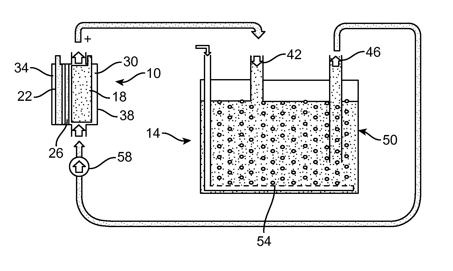
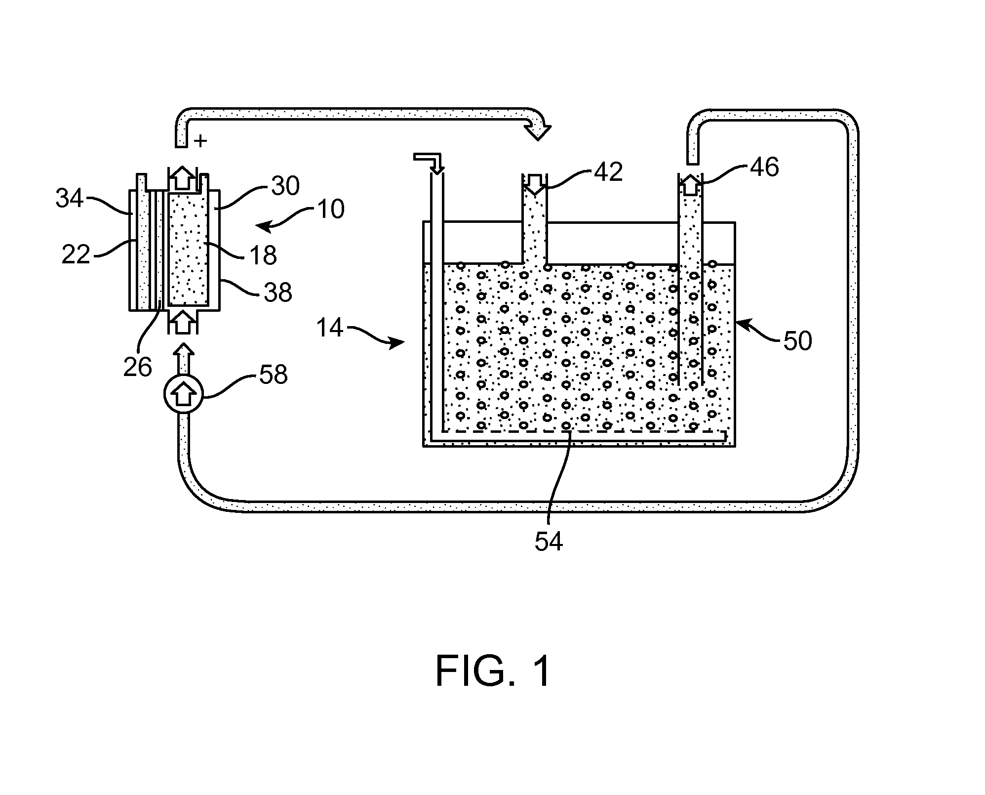
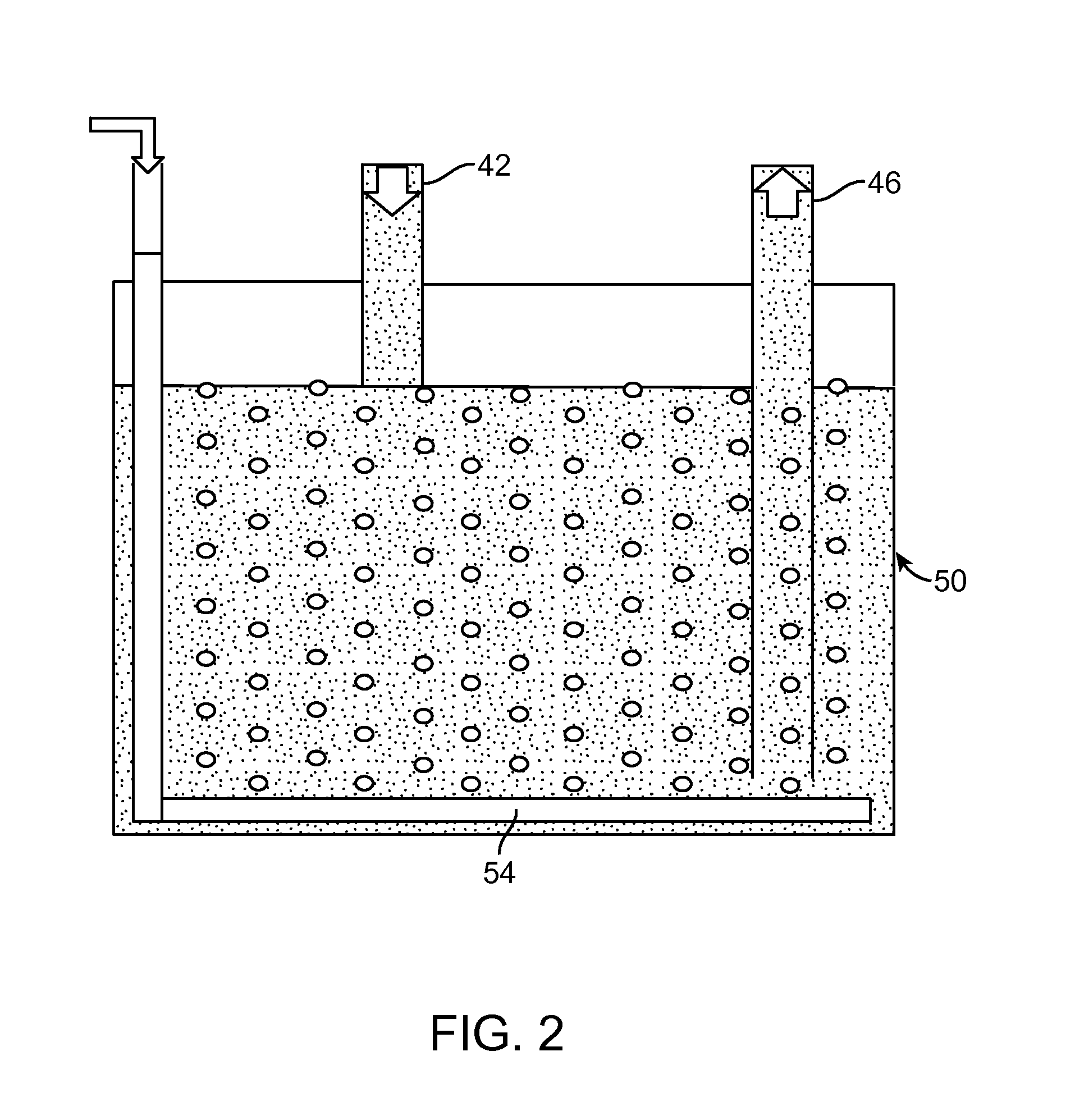
[0065]An experimental Li-air flow battery was prepared. The cathode electrode does not open directly to the atmosphere to receive the oxygen; instead it circulates the electrolyte continuously between the electrochemical reaction unit and electrolyte storage unit (FIG. 3). For example, during discharge, the fresh electrolyte which is saturated with oxygen is pumped into the electrochemical reaction unit, while the used electrolyte will be sent to the oxygen exchange unit to be refreshed. In the Li-air flow battery, the anode is a piece a Li-metal foil (Alfa Aesar, 99.9%, 0.75 mm thickness). A piece of separator (Celgard 2400, Celgard LLC, Charlotte N.C.) was placed between a Li-metal foil and a lithium-ion conducting glass-ceramic (LIC-GC) membrane (Ohara Inc., 0.15 mm thickness). The cathode is a carbon nanofoam. The aqueous electrolyte at the cathode and electrolyte container was made with 0.85 M CH3COOH (HOAc, Sigma Aldrich, ≧99.7%) and CH3COOLi (LiOAc, Sigma Aldrich) in deionize...


PUM


Abstract

A metal air flow battery includes an electrochemical reaction unit and an oxygen exchange unit. The electrochemical reaction unit includes an anode electrode, a cathode electrode, and an ionic conductive membrane between the anode and the cathode, an anode electrolyte, and a cathode electrolyte. The oxygen exchange unit contacts the cathode electrolyte with oxygen separate from the electrochemical reaction unit. At least one pump is provided for pumping cathode electrolyte between the electrochemical reaction unit and the oxygen exchange unit. A method for producing an electrical current is also disclosed.

Description

CROSS-REFERENCE TO RELATED APPLICATION[0001]This Application claims priority to U.S. Provisional Patent Application No. 61 / 641,676, filed May 2, 2012 and U.S. Provisional Patent Application No. 61 / 766,455, filed Feb. 19, 2013, the entirety of which are incorporated herein by reference.STATEMENT REGARDING FEDERALLY SPONSORED RESEARCH[0002]This invention was made with government support under contract No. CERDEC / GTS-S-11-396 awarded by the U.S. Army and US Department of Energy ARPA-E program to response proposal solicitation #: DE-FOA-0000670. The Government has certain rights in this invention.FIELD OF THE INVENTION[0003]The present invention relates to lithium ion batteries, and more particularly to metal air flow lithium ion batteries.BACKGROUND OF THE INVENTION[0004]Grid-connected renewable energy systems have experienced a rapid growth in the U.S. recently. Both wind and photovoltaic energy production have almost doubled in the last several years requiring new energy storage syst...

Claims


Application Information

Patent Timeline
IPC IPC(8): H01M12/08H01M4/90H01M8/04H01M50/77
CPCH01M12/08H01M2004/8689H01M4/9083H01M8/04276H01M4/382Y02E60/10Y02E60/50H01M50/77H01M4/96H01M8/20H01M2300/0002H01M2300/0037
Inventor ZHENG, JIAN-PINGANDREI, PETRUSHELLIKERI, ANNADANESHCHEN, XUJIE
Owner FLORIDA STATE UNIV RES FOUND INC
Learn More