
Nitrided steel member and manufacturing method thereof

a technology of nitrided steel and steel parts, which is applied in the direction of manufacturing tools, furnaces, heat treatment equipment, etc., can solve problems such as strained strains, and achieve the effect of excellent pitting resistance and low strain

Active Publication Date: 2015-02-26
DOWA THERMOTECH +2
View PDF1 Cites 19 Cited by
  • Summary
  • Abstract
  • Description
  • Claims
  • Application Information

AI Technical Summary

Benefits of technology

The patent text describes a way to make a nitrided steel that has better resistance to pitting and bending fatigue than a carburized steel. It also has low strain compared to carburized or carbonitrided steels.

Problems solved by technology

Especially in an internal gear, there has been a problem that it is likely to be strained because it is thin and large in diameter.

Method used


Image

  • Nitrided steel member and manufacturing method thereof
  • Nitrided steel member and manufacturing method thereof
  • Nitrided steel member and manufacturing method thereof

Examples


example 1

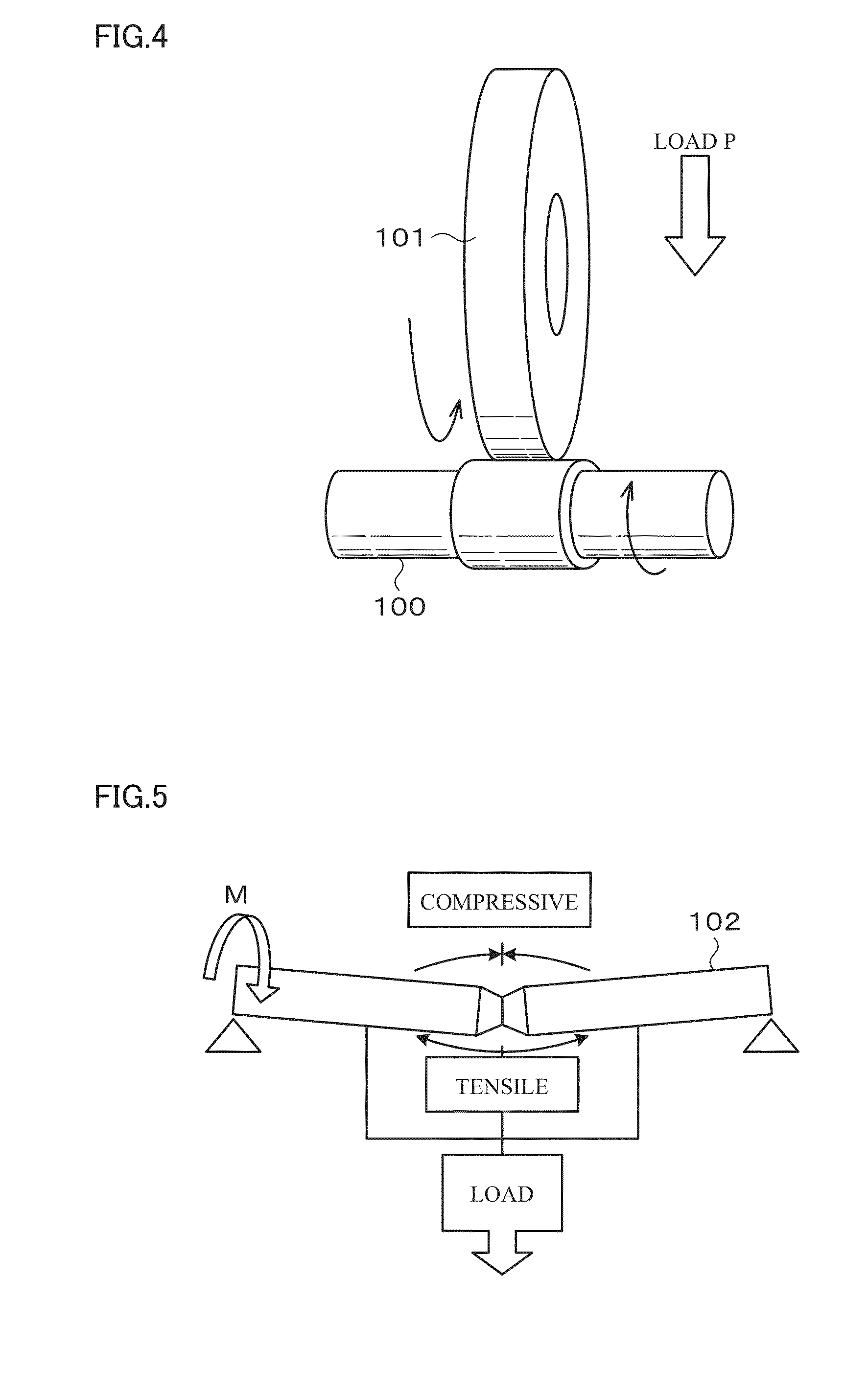
[0078]Samples of a steel member were prepared which each had a composition containing, by mass %, C: 0.07%, Si: 0.19%, Mn: 1.28%, P: 0.015%, S: 0.025%, Cr: 1.32%, Mo: 0.34%, V: 0.23%, Al: 0.030%, N: 0.0050%, O: 0.0015%, and the balance being Fe and impurities and whose Hs value was 2.34 and Hc value was 3.60. Further, the shapes of the samples were prepared for peel strength, nitridation quality confirmation (disk shape), a roller pitting test, an Ono-type rotating bending fatigue test, and gear strain amount measurement.

[0079]Next, the samples were subjected to vacuum cleaning as a pre-treatment of gas nitrocarburizing.

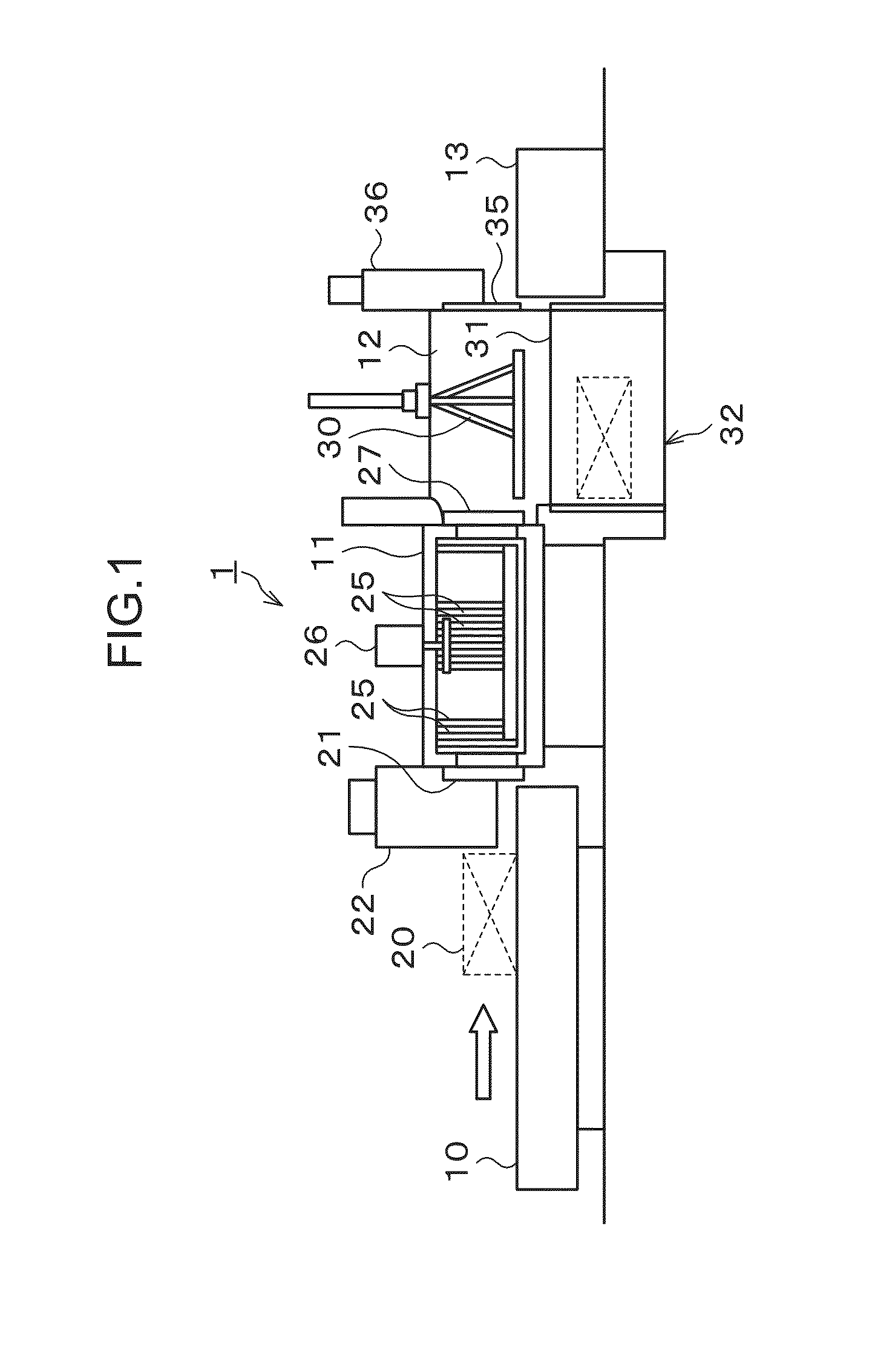
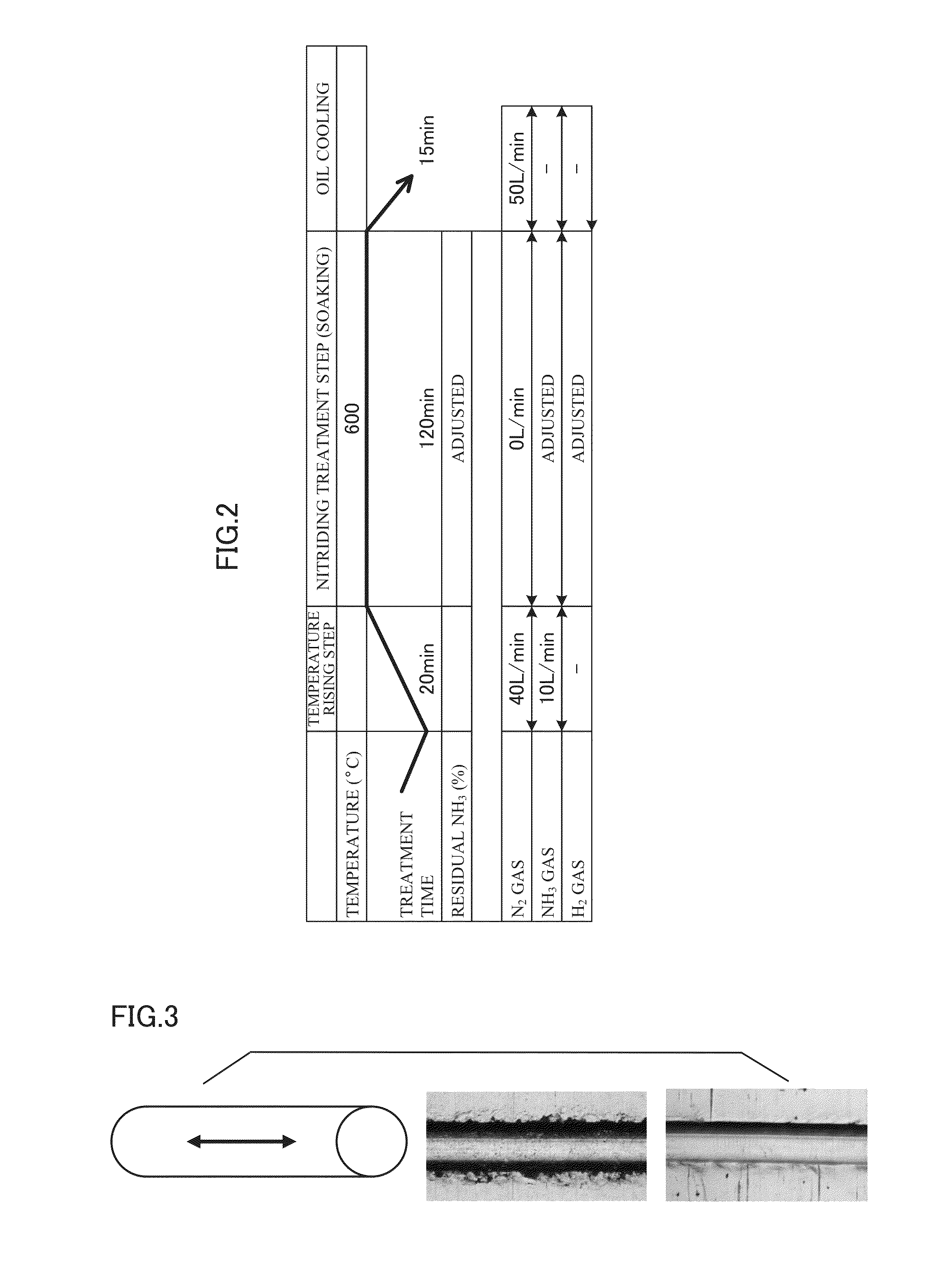
[0080]Next, a nitriding treatment of the samples was executed in a gas atmosphere. First, in a temperature rising step, flow rates of NH3 gas and N2 gas which were supplied to a furnace (heating chamber) were set to 0.01 m3 / min and 0.04 m3 / min respectively, and the temperature was increased up to a nitriding treatment temperature. As conditions of the subsequently ex...

example 2

[0082]Samples were prepared in the same manner as in the example 1 except that they each had a composition containing, by mass %, C: 0.07%, Si: 0.16%, Mn: 1.27%, P: 0.025%, S: 0.014%, Cr: 0.90%, Mo: 0.20%, Al: 0.027%, N: 0.0080%, O: 0.0009%, and the balance being Fe and impurities and an Hs value was 1.31 and Hc value was 2.64. Next, a pre-treatment and a nitriding treatment were executed under the same conditions as those of the example 1 to form an iron nitride compound on a surface of each of the samples, and thereafter the evaluations were conducted.

example 3

[0083]Samples were prepared in the same manner as in the example 1 except that they each had a composition containing, by mass %, C: 0.09%, Si: 0.18%, Mn: 0.70%, P: 0.009%, S: 0.014%, Cr: 1.20%, V: 0.13%, Al: 0.030%, N: 0.0045%, O: 0.0016%, and the balance being Fe and impurities and an Hs value was 1.73 and an Hc value was 2.59. Next, a pre-treatment and a nitriding treatment were executed under the same conditions as those of the example 1 to form an iron nitride compound on a surface of each of the samples, and thereafter the evaluations were conducted.


PUM

PropertyMeasurementUnit
thicknessaaaaaaaaaa
temperatureaaaaaaaaaa
timeaaaaaaaaaa

Abstract

A nitrided steel member including an iron nitride compound layer formed on a surface of a steel member having predetermined components, wherein: in X-ray diffraction peak intensity IFe4N (111) of a (111) crystal plane of Fe4N and X-ray diffraction peak intensity IFe3N (111) of a (111) crystal plane of Fe3N, which are measured on a surface of the nitrided steel member by X-ray diffraction, an intensity ratio expressed by IFe4N (111) / {IFe4N (111)+IFe3N (111)} is 0.5 or more; Vickers hardness of the iron nitride compound layer is 900 or less, Vickers hardness of a base metal immediately under the iron nitride compound layer is 700 or more, and a difference between the Vickers hardness of the iron nitride compound layer and the Vickers hardness of the base metal is 150 or less; and a thickness of the iron nitride compound layer is 2 to 17 μm.

Description

TECHNICAL FIELD[0001]The present invention relates to a nitrided steel member whose surface is nitrided by a nitriding treatment in a gas atmosphere and to a manufacturing method thereof. It further relates to a high-strength nitrided steel member that is used as a gear of an automobile or the like and has improved pitting resistance and bending fatigue strength.BACKGROUND ART[0002]A gear that is used in, for example, a transmission for an automobile is required to have high pitting resistance and bending fatigue strength. In order to meet such a requirement, a carburizing treatment has conventionally been widely performed as a method of strengthening a steel member such as a gear. Further, with the aim of further improving the pitting resistance, there has been proposed an invention relating to achievement of high strength by a carbonitriding treatment (Patent Document 1). On the other hand, in a planetary gear, due to its high engagement degree, tooth profile accuracy (strain) has...

Claims


Application Information

Patent Timeline
Patent Type & Authority Applications(United States)
IPC IPC(8): C23C8/26C22C38/22C22C38/06C21D9/32C22C38/02C22C38/00C21D1/06C22C38/24C22C38/04
CPCC23C8/26C22C38/24C22C38/22C22C38/06C21D9/32C22C38/02C22C38/002C22C38/001C21D1/06C22C38/04C21D1/76C21D6/02C21D9/28C21D2201/05C21D2211/004C21D2221/00C22C38/00F16H55/06
Inventor SHIMIZU, YUICHIROKOBAYASHI, ATSUSHIMAEDA, SUSUMUKANAYAMA, MASAOIMATAKA, HIDEKIYUYA, MASATOGYOTOKU, YUYAAKIMOTO, KIYOTAKA
Owner DOWA THERMOTECH
Learn More