
Processes and apparatuses for removal of carbon, phosphorus and nitrogen

a technology of carbon, phosphorus and nitrogen, applied in the direction of biological water/sewage treatment, sustainable biological treatment, treatment water, etc., can solve the problems of challenging to eliminate all these nutrients in one reactor, environmental hazards of wastewater treatment plants, etc., to reduce additional infrastructure related costs, improve the performance and effluent quality, and reduce the effect of energy consumption

Active Publication Date: 2015-01-01
VALORBEC S E C +1
View PDF2 Cites 25 Cited by
  • Summary
  • Abstract
  • Description
  • Claims
  • Application Information

AI Technical Summary

Benefits of technology

This patent is about a process for upgrading a wastewater treatment facility using a single reactor. The process involves maintaining an adequate oxidation-reduction potential in the reactor, which allows for the removal of carbon, nitrogen, and phosphorus from the wastewater and the production of a treated wastewater and solids mixture. The process requires the immersion of electrodes into the activated sludge basin and is energy-efficient, with low current density and intermittent exposure to the electrical field. Additionally, the process can improve sludge characteristics and remove major environmental hazards. This upgrade process is cost-effective and can be easily integrated into existing facilities.

Problems solved by technology

Effluents from wastewater treatment plants pose environmental hazard to the receiving water bodies mainly due to the contents of carbon, phosphorus and nitrogen (C, P and N), particularly if the plant is not designed to perform tertiary nutrient (N, P) treatment.
Carbon source is added into the anoxic reactor to sustain the heterotrophic denitrifiers responsible for conversion of nitrate into gas, which is costly.
The elimination of all these nutrients in one single reactor is a challenging task.

Method used


Image

  • Processes and apparatuses for removal of carbon, phosphorus and nitrogen
  • Processes and apparatuses for removal of carbon, phosphorus and nitrogen
  • Processes and apparatuses for removal of carbon, phosphorus and nitrogen

Examples


example 1

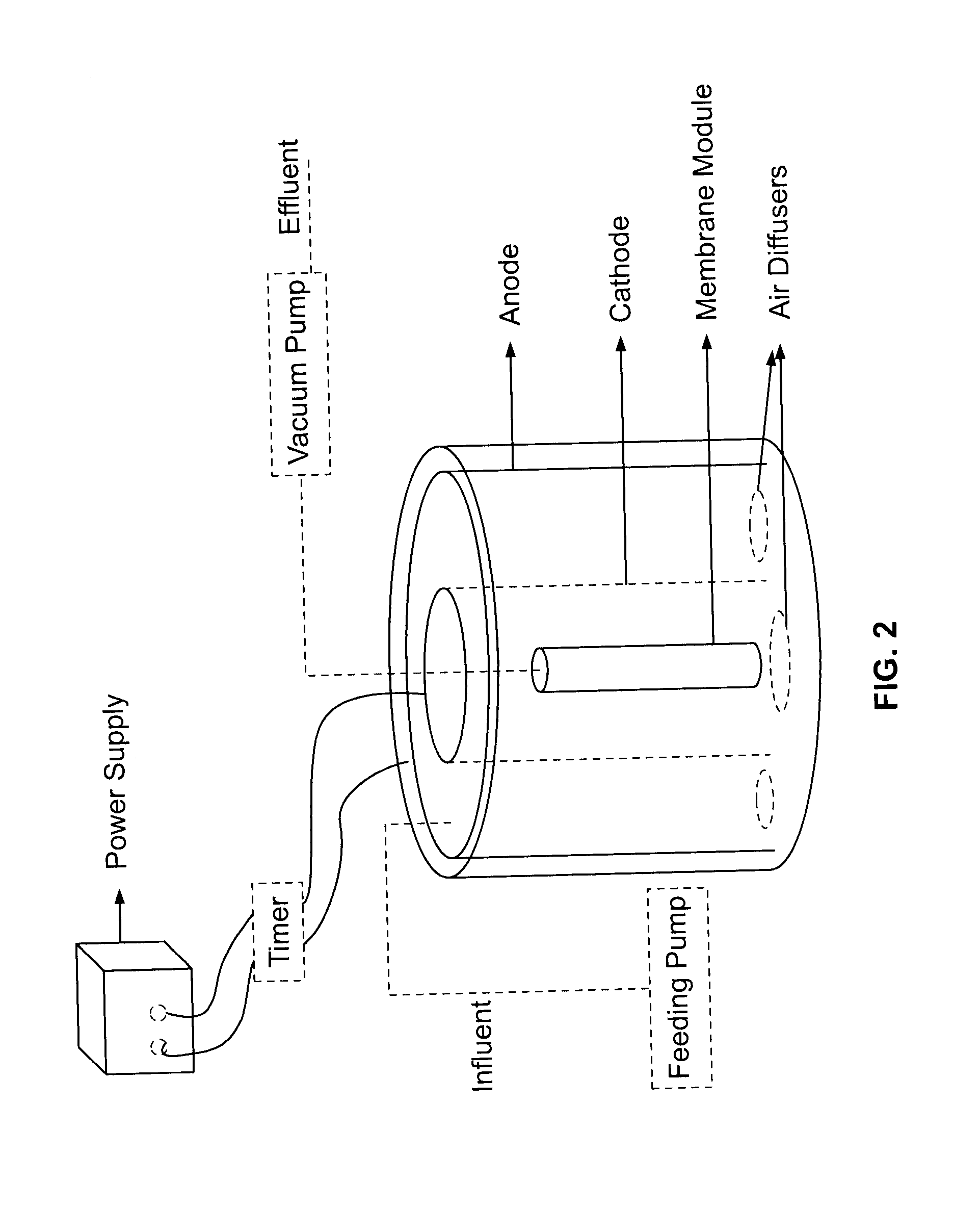
[0079]In this experiment, one submerged membrane electro-bioreactor SMEBR (FIG. 2) and one submerged membrane bioreactor (MBR) without electrical field to serve as a control were operated simultaneously. They were fed with the same mixture comprising synthetic wastewater and activated sludge and run at the same operating conditions to create perfect comparing conditions. SMEBR outer body was composed of a cylindrical polyethylene container (20 L). The design is adequate to patented SMEBR system (Elektorowicz et al., 2009). In the middle of this reactor, a hollow fiber ultrafiltration membrane module was placed vertically. Air diffusers were inserted on top and below the membrane to provide air intensity enough to mitigate fouling on the membrane surface. Two cylindrical perforated electrodes (aluminum anode and stainless steel cathode) were placed around the membrane as demonstrated in FIG. 2. Direct current power supply connected with an electrical timer was applied to provide the ...

example 2

[0092]Further tests have been made for simultaneously removing of carbon, phosphorous and nitrogen in a rectangular electro-bioreactor. The lab scale tests were carried out in rectangular 15 L reactor where three modules hollow fiber membranes were installed after two pairs of electrodes submerged in wastewater. Both aluminum anodes and stainless steel cathodes were perforated to permit on free flow throughout from point of wastewater supply towards membranes. Applied CD was less than 15 A / m2 and a ratio of electrical zone to total volume of the electro-bioreactor was no more than of 0.4. The continuous flow reactor was fed with synthetic wastewater inoculated with activated sludge sampled at wastewater treatment plant. The influent of synthetic wastewater contained COD at the range of 892-999 mg / L as well as 16.8-17.4 mg NH3—N / L, 0.23-0.24 mg NO3—N / L and 15.3-22.1 mg PO4 / L.

[0093]The reactor has run for 5 months at a constant flow of 45 L / d and SRT of 15 days. The system was able to...

example 3

[0094]Further tests have been made in order to verify the possibility of removing metals by using a process similar to the process of Example 1 using a SMEBR. A PVC cylindrical reactor (235 L), two cylindrical electrodes connected to a low DC power supply (intermittent supply of electrical field), and a hollow fiber microfiltration membrane (MUNC-600A, Microza, Asahi Kasei Chem. Corp., Japan) were used (see FIG. 2). The membrane had an effective surface area of 12.5 m2, a pore size of 0.1 μm, and the module was equipped with a built-in bottom air diffuser for scouring. Several fine bubble air diffusers were also placed at the bottom of the reactor to supply the oxygen required for both mixing and microbial activity. SMEBR was continuously fed with pre-screened raw municipal wastewater containing metals (see Tables 2 and 3) redirected from the influent channel at a flow rate of 550 L / d for 7 weeks. SRT and HRT were 10 d and 11 h, respectively. SMEBR operated under constant current de...


PUM


Abstract

There are provided processes for treating wastewater. The processes can comprise treating a mixture comprising the wastewater and an activated sludge, in a single reactor, with an electric current having a density of less than about 55 A / m2, by means of at least one anode and at least one cathode that define therebetween an electrical zone for treating the mixture; exposing the mixture to an intermittent ON / OFF electrical exposure mode to the electric current in which an OFF period of time is about 1 to about 10 times longer than an ON period of time; and maintaining an adequate oxidation-reduction potential in the single reactor. Such processes allow for substantial removal of carbon, nitrogen and phosphorus from the wastewater in the single reactor of various forms and for obtaining another mixture comprising a treated wastewater and solids.

Description

CROSS-REFERENCE TO RELATED APPLICATIONS[0001]The present application claims priority on U.S. 61 / 596,471 filed on Feb. 8, 2012. This document is hereby incorporated by reference in its entirety.TECHNICAL FIELD[0002]The present disclosure relates to improvements in the field of waste material treatment. For example, it relates to processes and apparatuses for wastewater treatment.BACKGROUND OF THE DISCLOSURE[0003]Effluents from wastewater treatment plants pose environmental hazard to the receiving water bodies mainly due to the contents of carbon, phosphorus and nitrogen (C, P and N), particularly if the plant is not designed to perform tertiary nutrient (N, P) treatment. These nutrients are the major stimulants of eutrophication and they should be eliminated from the effluent before discharge into the aquatic environment. Currently, new treatment facilities are designed to remove these nutrients to extremely low levels as a part of sustainable water management. The ever more stringen...

Claims


Application Information

Patent Timeline
IPC IPC(8): C02F1/467
CPCC02F1/4672C02F2303/04C02F2203/004C02F2103/34C02F1/463C02F3/005C02F3/20C02F3/302C02F2001/46171C02F2201/003C02F2201/4614C02F2201/4615C02F2201/46155C02F2201/46175C02F2209/04C02F2209/08C02F2209/14C02F2209/16C02F2209/18C02F2209/44Y02W10/15C02F3/1273C02F3/301C02F2001/46133C02F2209/22C02F3/307Y02W10/10
Inventor IBEID, SHARIFELEKTOROWICZ, MARIAOLESZKIEWICZ, JAN
Owner VALORBEC S E C
Learn More