
Thermally-assisted magnetic recording head and method of manufacturing the same

a technology of magnetic recording head and magnetic recording head, which is applied in the field of thermally assisted magnetic recording head and method of manufacturing the same, can solve the problems of increasing the coercivity of the magnetic disk, reducing the thermal stability of the magnetization of the magnetic microparticle, and affecting the recording of information, so as to prevent the effect of recession and increase the density of the first region

Inactive Publication Date: 2014-08-21
TDK CORPARATION
View PDF6 Cites 4 Cited by
  • Summary
  • Abstract
  • Description
  • Claims
  • Application Information

AI Technical Summary

Benefits of technology

The invention relates to a thermally-assisted magnetic recording head and its components. The technical effects of the invention include the suppression of agglomeration in the high-density region of the head, which prevents recession of the one end in the first region exposed on the air-bearing surface, and efficient generation of stronger near-field light in the vicinity of the one end without increasing incidence energy, resulting in higher-density magnetic recording without degrading recording performance. The density of the high-density region is equal to or greater than about 1.1 times the density of the second region, and the size of the first region in a direction orthogonal to the air-bearing surface is equal to or less than about 100 nanometers. The heating is performed before the formation of the air-bearing surface to apply the stress to the first region from the second region utilizing the thermal expansion of the second region to increase its density. The size of the first region in a direction orthogonal to the air-bearing surface is equal to or less than about 100 nanometers. The heating may be performed by generating near-field light from the plasmon generator to effectively heat the section where a rise in temperature is generated significantly upon operation. The size of the first region removed by polishing is equal to or less than about 100 nm. The high-density region having a density equal to or greater than about 1.1 times the density of the second region may be formed in the first region by the heating. The heating temperature should be set between about 200 degrees centigrade and about 250 degrees centigrade to improve the density of the first region and prevent adverse effect on other structures.

Problems solved by technology

However, when the magnetic microparticles are made small in size, thermal stability of the magnetization of the magnetic microparticles is disadvantageously lowered with decreasing volume of the magnetic microparticles.
However, increasing the anisotropy energy of the magnetic microparticle leads to increase in the coercivity of the magnetic disk.
As a result, difficulty occurs in the existing magnetic head in that the information recording becomes difficult.
In the method of directly applying light to a plasmon generator, however, the plasmon generator itself overheats and accordingly deforms depending on usage environment or conditions, making it difficult to achieve practical realization.
Therefore, sufficiently stabilizing a crystalline structure of a constituent material of the plasmon generator to sufficiently suppress the agglomeration thereof upon operation is virtually difficult.
When such agglomeration occurs, an end section of the plasmon generator is recessed from the ABS and is away from a magnetic recording medium, incurring a decrease in recording performance.

Method used


Image

  • Thermally-assisted magnetic recording head and method of manufacturing the same
  • Thermally-assisted magnetic recording head and method of manufacturing the same
  • Thermally-assisted magnetic recording head and method of manufacturing the same

Examples


embodiment

[0033]Hereinafter, an embodiment of the invention will be described in detail with reference to the drawings.

[1. Configuration of Magnetic Disk Unit]

[0034]First, referring to FIG. 1 and FIG. 2, a configuration of a magnetic disk unit according to an embodiment of the invention will be described below.

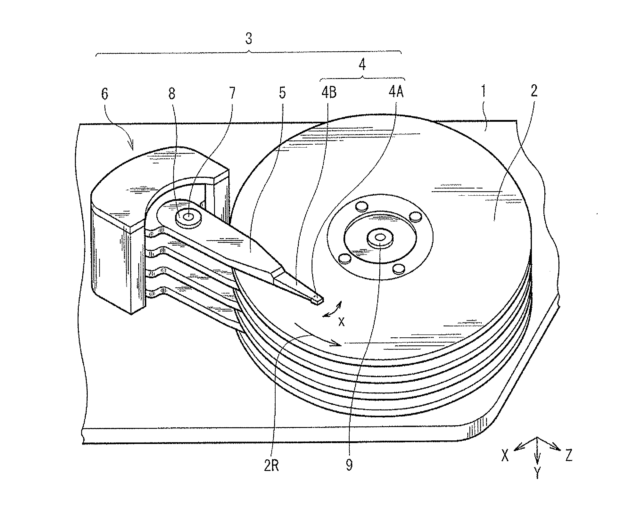
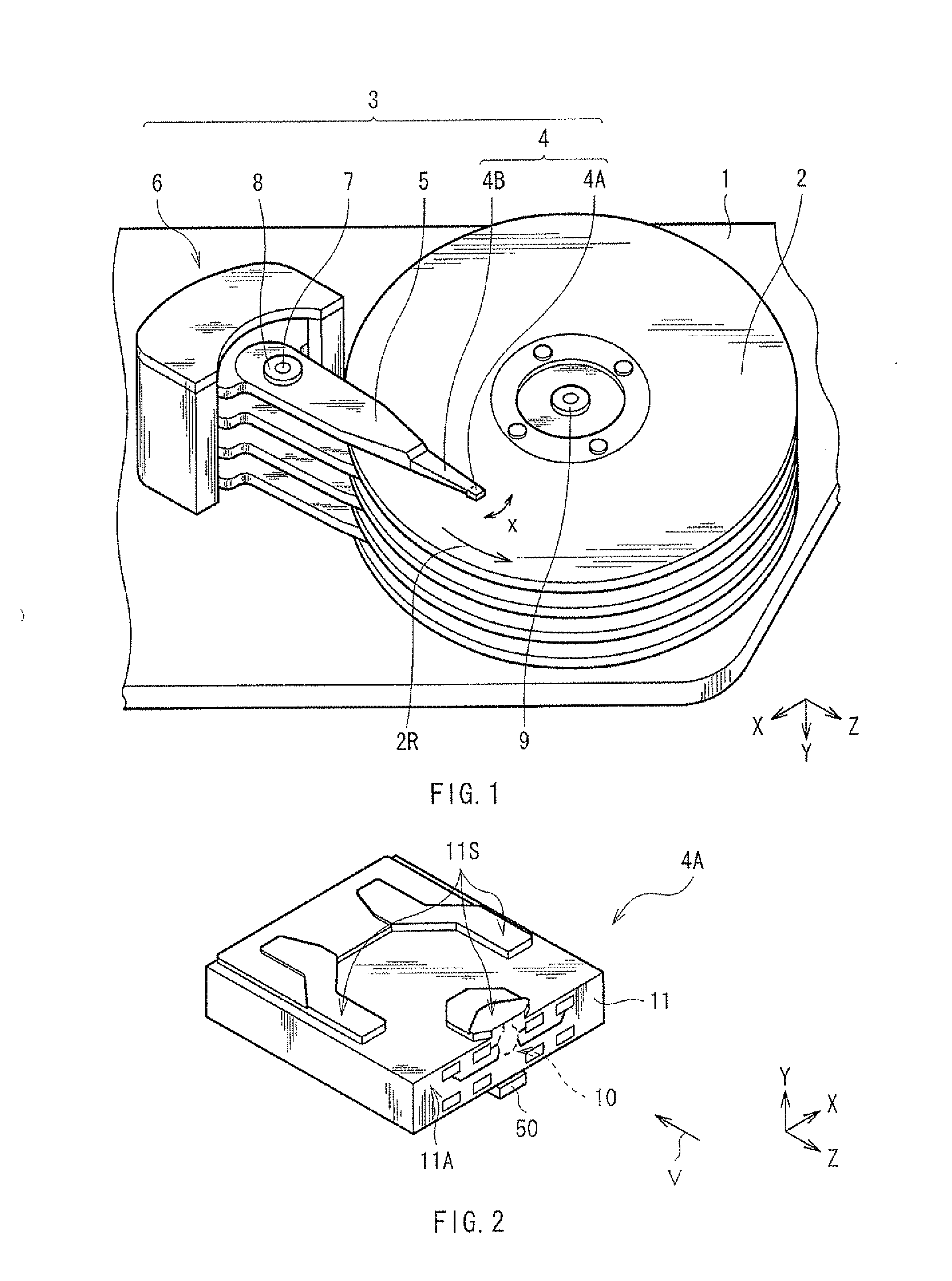
[0035]FIG. 1 is a perspective view illustrating an internal configuration of the magnetic disk unit according to the present embodiment. The magnetic disk unit adopts a load-unload (load / unload) scheme as a driving system, and includes, in a housing 1 for example, a magnetic disk 2 as a magnetic recording medium in which information is to be written, and a head arm assembly (HAA) 3 for writing information in the magnetic disk 2 and reading the information therefrom. The HAA 3 includes a head gimbals assembly (HGA)4, an arm 5 supporting a base of the HGA 4, and a driver 6 as a drive power source for allowing the arm 5 to pivot. The HGA 4 includes a thermally-assisted magnetic head device...

examples

[0095]Examples of the invention will be described in detail.

1. Lifetime Test (1)

experiment 1

Samples 1-1 to 1-6

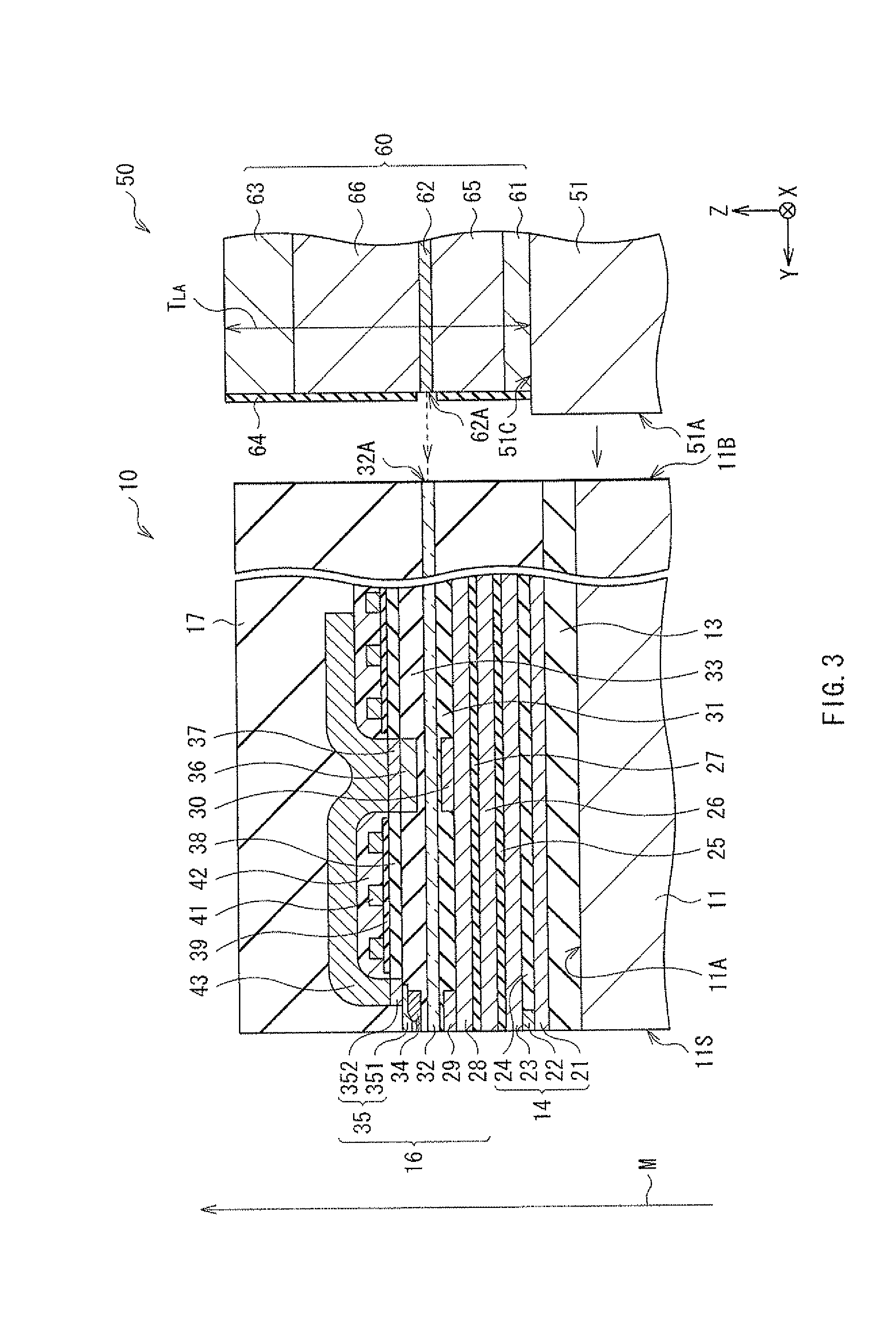
[0096]A test on lifetime was conducted, at the following conditions, on the magnetic recording reproducing head 10 of the invention, obtained through subjecting the plasmon generator 34 in which the length L1 and the length L4 were both 100 nm to a heat treatment and polishing the same, as illustrated in FIG. 11A. Specifically, heat with power equivalent to 2.5 times as much as that used in an actual write operation was applied to the magnetic recording reproducing head 10, following which writing of information was performed with the power used in the actual write operation, to measure the time taken for a signal-to-noise ratio (SNR) of a read signal to cause a 2 dB decrease for an initial value. Also, the plasmon generator 34 was entirely formed by Au, and a temperature of 220 degrees centigrade was maintained for two hours in the heat treatment.


PUM

PropertyMeasurementUnit
sizeaaaaaaaaaa
temperatureaaaaaaaaaa
sizeaaaaaaaaaa

Abstract

This thermally-assisted magnetic recording head includes: a waveguide; a magnetic pole; and a plasmon generator having a first region and a second region, in which the first region has an one end exposed on an air-bearing surface and another end located on an opposite side of the air-bearing surface, and in which the second region is coupled to the another end of the first region and has a volume greater than a volume of the first region. The first region includes a high-density region having a density that is greater than the density of the second region.

Description

BACKGROUND OF THE INVENTION[0001]1. Field of the Invention[0002]The invention relates to a thermally-assisted magnetic recording head used in thermally-assisted magnetic recording in which near-field light is applied to lower a coercivity of a magnetic recording medium so as to perform recording of information, and to a method of manufacturing the thermally-assisted magnetic recording head.[0003]2. Description of Related Art[0004]A magnetic disk unit has been used for writing and reading magnetic information (hereinafter, simply referred to as information). The magnetic disk unit includes, in a housing thereof for example, a magnetic disk in which information is stored, and a magnetic recording reproducing head that records information into the magnetic disk and reproduces information stored in the magnetic disk. The magnetic disk is supported by a rotary shaft of a spindle motor, which is fixed to the housing, and rotates around the rotary shaft. On the other hand, the magnetic rec...

Claims


Application Information

Patent Timeline
Patent Type & Authority Applications(United States)
IPC IPC(8): G11B13/04G11B5/127
CPCG11B5/1272G11B13/04G11B5/314G11B5/6088G11B2005/0021G02B6/1226G11B5/3173Y10T29/49048
Inventor SHIMAZAWA, KOJI
Owner TDK CORPARATION
Learn More