
Quenched and partitioned high-carbon steel wire

a high-carbon steel wire, partitioned technology, applied in the direction of low internal friction springs, magnetic materials, magnetic bodies, etc., can solve the problems of high cost of steel wires of wo2011/004913, process has not yet been applied to high-carbon steel wires, and the percentage of retained austenite is less, so as to improve the resistance to fracture and damage tolerance, good contact fatigue properties, hardness and ductility

Inactive Publication Date: 2014-08-14
NV BEKAERT SA
View PDF5 Cites 10 Cited by
  • Summary
  • Abstract
  • Description
  • Claims
  • Application Information

AI Technical Summary

Benefits of technology

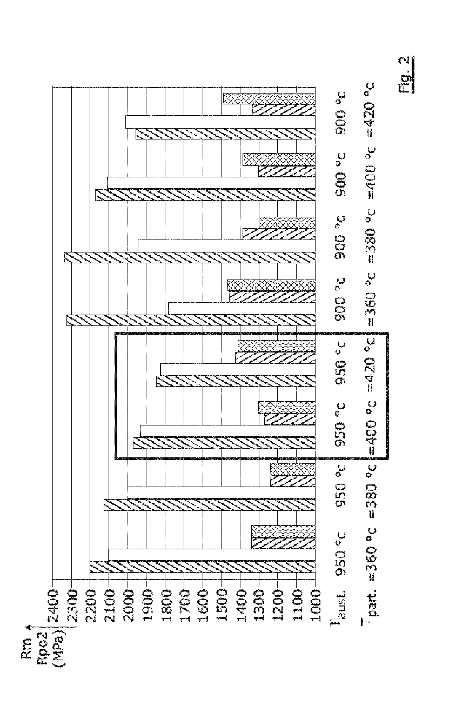
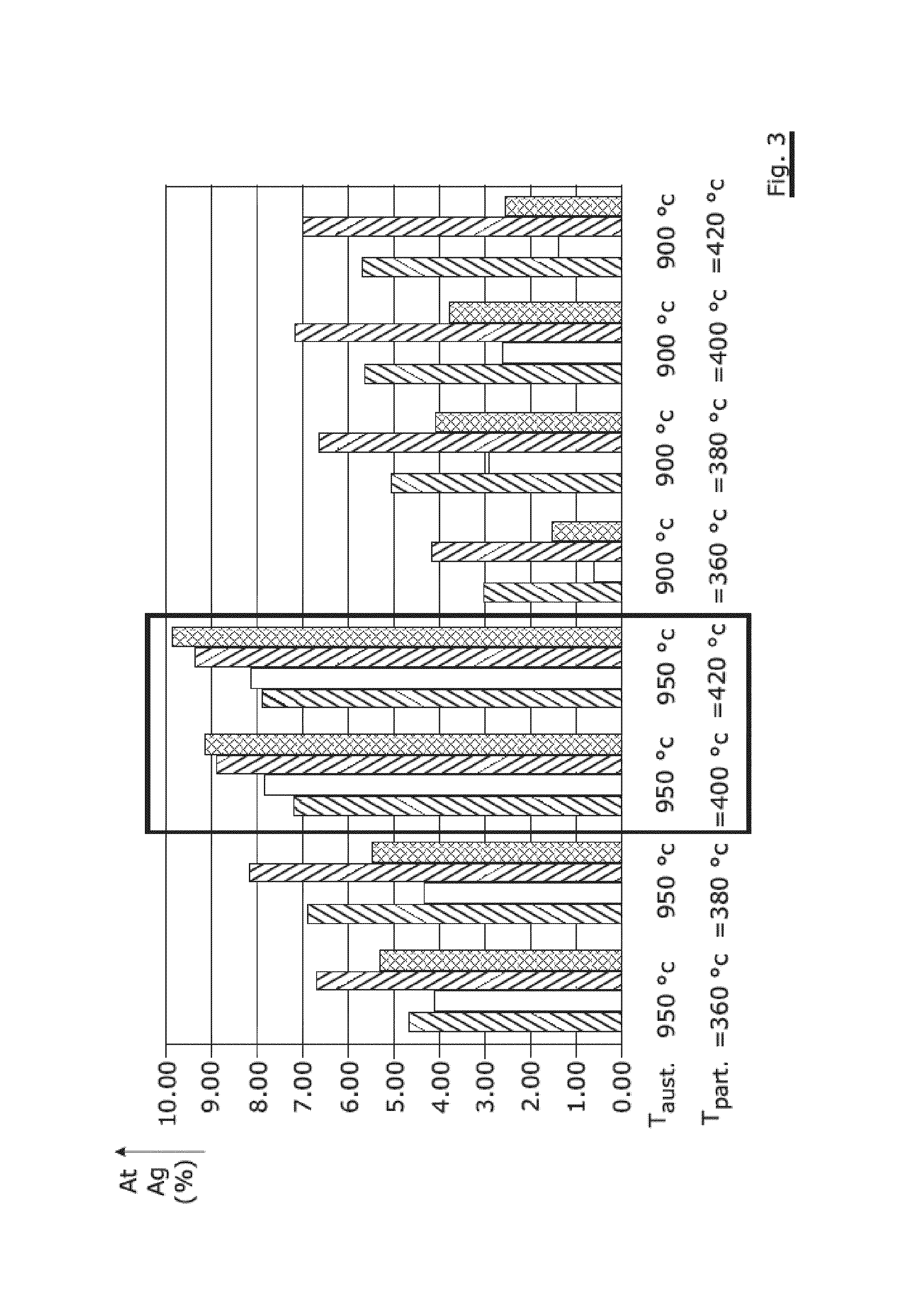
This patent describes a new type of steel wire that has very high strength and ductility, making it very effective for cold deformation. This steel wire can be produced using an available chemical composition without expensive microalloying elements. The retained austenite in the steel wire increases its resistance to fracture and damage tolerance in rolling or sliding contact fatigue. The combination of martensite and carbon enriched retained austenite ensures both hardness and ductility, as well as good contact fatigue properties.

Problems solved by technology

This low start temperature is the cause of an incomplete martensite transformation resulting in a percentage of retained austenite.
The relative high amount of alloying elements makes the steel wire of WO2011 / 004913 more expensive.
However, this process has not yet been applied to high-carbon steel wires with a diameter ranging from 1.0 mm to 6.0 mm and with a plain carbon steel composition.
The steel composition and the particular process conditions mentioned in WO2004 / 022794 are, however, not suitable for high-carbon steel wires.
A microstructure containing more than 5vol % retained austenite is mentioned to be not suitable for spring application because the resistance to permanent set will decrease due to martensite formation.
The process conditions mentioned in WO2009 / 082107, and particularly the ten minutes long time needed for partitioning, makes this not economical for high-carbon steel wires with a diameter between 1.0 mm and 6.0 mm.

Method used


Image

  • Quenched and partitioned high-carbon steel wire
  • Quenched and partitioned high-carbon steel wire
  • Quenched and partitioned high-carbon steel wire

Examples


Embodiment Construction

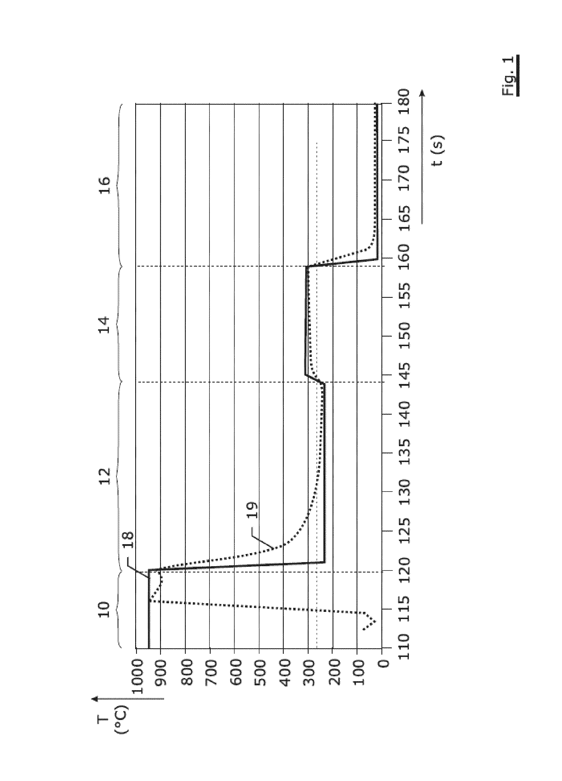
[0062]FIG. 1 illustrates a suitable temperature versus time curve applied to a drawn steel wire with a diameter of 3.60 mm and with following steel composition:[0063]% C=0.55[0064]% Si=1.62[0065]% Mn=0.70[0066]% Cr=0.77

the balance being iron and unavoidable impurities (% S and % P below 0.020 and weight percentages of other elements below 0.10)

[0067]The starting temperature of martensite transformation Ms of this steel is about 280° C. and the temperature Mf, at which martensite formation ends is about 170° C.

[0068]The various steps of the process are as follows:[0069]a first austenitizing step (10) during which the steel wire stays in a furnace at about 950° C. during 120 seconds,[0070]a second quenching step (12) for partial martensite transformation at a temperature below 280° C. during less than 25 seconds;[0071]a third partitioning step (14) for moving carbon atoms from the martensite phase to the austenite phase to stabilize this at a temperature above 300° C. during about 15 ...


PUM

PropertyMeasurementUnit
Temperatureaaaaaaaaaa

Abstract

A high-carbon steel wire has as steel composition: a carbon content ranging from 0.40 weight percent to 0.85 weight percent, a silicon content ranging from 1.0 weight percent to 2.0 weight percent, a manganese content ranging from 0.40 weight percent to 1.0 weight percent, and a chromium content ranging from 0.0 weight percent to 1.0 weight percent. The remainder is iron. This steel wire has as metallurgical structure a volume percentage of retained austenite ranging from 4 percent to 20 percent, while the remainder is tempered primary martensite and untempered secondary martensite. The steel wire is obtained by partitioning after quenching.

Description

TECHNICAL FIELD[0001]The present invention relates to a high-carbon steel wire, to a process for manufacturing a high-carbon steel wire and to various uses or applications of such a high-carbon steel wire as spring wire, rope wire, wire in flexible pipe and wire in impact absorption applications.BACKGROUND ART[0002]WO2011 / 004913 discloses a steel wire for a high-strength spring. The steel wire has following composition: carbon between 0.67% and 0.75%, silicon between 2.0% and 2.5%, manganese between 0.5% and 1.2%, chromium between 0.8% and 1.3%, vanadium between 0.03% and 0.20%, molybdenum between 0.05% and 0.25%, tungsten between 0.05% and 0.30% with a particular relationship between manganese and vanadium and between molybdenum and tungsten. All percentages are percentages by weight. The metallographic structure of this steel wire comprises between 6% and 15% of retained austenite with a remainder of martensite.[0003]This steel wire is manufactured by first austenitizing the steel...

Claims


Application Information

Patent Timeline
IPC IPC(8): C21D8/06F16F7/00F16F1/02F16L11/02D07B1/06
CPCC21D8/065F16L11/02D07B2201/2009F16F1/021F16F7/00D07B1/068C21D8/06C21D9/52C21D9/525C21D1/19C21D1/22C22C38/02C22C38/04C22C38/18C21D2211/001C21D2211/008Y10T428/12
Inventor MESPLONT, CHRISTOPHEVAN RAEMDONCK, WALTHER
Owner NV BEKAERT SA
Learn More