Method and apparatus for acquiring nanostructured coating by effect of laser-induced continuous explosion shock wave

a laser-induced continuous explosion and nano-structure technology, applied in the field of laser technology and surface strengthening, can solve the problems of high temperature of substrate materials, high material temperature, and many damages, and achieve the effects of improving the fatigue life of materials, reducing the number of damage, and reducing the damag

Active Publication Date: 2014-07-24
JIANGSU UNIV
View PDF1 Cites 2 Cited by
  • Summary
  • Abstract
  • Description
  • Claims
  • Application Information

AI Technical Summary

Benefits of technology

[0005]By a method for acquiring a nanostructured coating disclosed by the present disclosure, the disadvantages mentioned above may be overcome, and a nanostructured coating may be obtained simply and quickly with remarkable effect and little pollution. Here, a continuous explosion shock wave induced by an intense laser beam with high power density and short pulse is utilized to embed powdery nanoparticles into a surface of metal materials, so that a dense nanostructured protection layer is formed on the surface. Hence, the corrosion resistance, abrasion resistance, oxidation resistance and fatigue life of the materials are improved. Compared with a conventional laser shock strengthening technology, a high pressure resistant glass pipe designed in the method may realize chain explosion of a black paint plasma, so that the rate and size of an explosion wave may be improved significantly.
[0006]In embodiments of the present invention, a high pressure resistant glass pipe is designed to induce an energy absorption material to perform chain ionization and explosion to generate an explosion wave, and to constrain the diffusion and attenuation of the explosion wave. The high pressure resistant glass pipe is made from K9 glass and is in a zigzagging switchback shape, and the switchback locations thereof are round right-angle corners. The inner diameter of an upper opening of the pipe is the same as that of the pulse laser spot. As the spot is adjustable, the high pressure resistant glass pipe is designed in a series of specifications: the inner diameter of the lower opening of the pipe is 3 mm less than that of the upper opening thereof; the upper end of the pipe is closed while the lower end thereof is open; the thickness of the pipe is 6 mm; and, the total length of the pipe is 40 mm. If the pipe is too long, the shock wave has a large attenuation; however, if the pipe is too short, the chain explosion shock wave can not have a required value. The inner wall of the pipe is a laser reflector for reflecting the laser beam which is not absorbed by the energy absorption material, so that the loss of energy is avoided. The reflective mirror at each corner reflects the laser beam to provide intermediate energy support for the chain explosion process. The reflector on the inner wall of the pipe is coated with a layer of energy absorption material (black paint, aluminum powder, etc.) strip, to ensure that each switchback location is coated with the energy absorption material. The glass pipe is encapsulated within a rectangular glass box, to be clamped conveniently by a manipulator.
[0007]When the intense laser beam with high power density and short pulse shocks the surface of the energy absorption coating at the upper opening of the high pressure resistant glass pipe, the coating particles absorb a part of energy of the high-energy laser beam to result in instantaneous vaporization, breakdown and ionization and then generate a plasma. Radiated by the subsequent laser beam, the plasma quickly accumulates energy and initiates expanding explosion to form an initial plasma explosion shock wave which is to be transmitted in the high pressure resistant glass pipe. With quite high temperature and energy, the generated plasma excites and induces adjacent coating particles to have the same process of vaporization by combustion, ionization and expanding explosion. The high-energy laser beam not absorbed is reflected onto the coating by the inner wall of the high pressure resistant glass pipe to vaporize and ionize the coating material, thereby providing energy support for the continuous chain explosion. This process is repeated along the energy absorption coating strip on the inner wall of the high pressure resistant glass pipe all the time, whereby a plasma cloud is formed. The explosion shock waves are continuously superimposed layer upon layer; furthermore, as the reaction time is extremely short (nanosecond), the attenuation of the shock wave is relatively small. The shock wave pressure at the lower opening jumps apparently (up to 103-105 GPa). The high pressure resistant glass pipe plays a role of enhancing the shock wave pressure. The intense shock wave formed during the chain explosion process embeds nanoparticles into a surface of an alloy material thus to form a nanoparticle coating. At the same moment of acquiring a nanoparticle coating, the peak pressure of the shock wave reaching the workpiece is higher than a dynamic yield strength of the metal material, so a strong plastic strain and a high density dislocation occur on the surface and there is a large residual pressure stress generated on the surface, thus the anti-fatigue performance of the material is improved effectively.
[0008]An apparatus disclosed by the present invention comprises: a high-power laser device, a three-degree-of-freedom manipulator, an infrared location calibrator, a 45° full-reflector, focusing lenses, an upper workpiece locating and clamping block, a workpiece, a controller for the workpiece clamping device, a lateral workpiece locating and clamping block, an X / Y-axis workpiece support plate, a workbench, a computer and a high pressure resistant glass pipe. The computer controls the laser device, the X / Y-axis workpiece support plate and the three-degree-of-freedom manipulator. The manipulator is located on the workbench. The high pressure resistant glass pipe is clamped by the manipulator. The upper end of the glass pipe is closed, while the lower end thereof is an inverted conical opening. The workpiece clamping device controller controls the movement and application of force of the workpiece locating and clamping block.
[0012]2. compared with a deposition method or a method for electroplating nanoparticles to a substrate material, the method disclosed by the present invention has simple technological process and high processing speed, and may embed nanoparticles into a surface of the substrate material quickly;
[0015]5. at the same moment of acquiring a nanoparticle coating, the peak pressure of the shock wave reaching the workpiece is higher than a dynamic yield strength of the metal material, so a strong plastic strain and a high density dislocation occur under the effect of high strain rate and there is a large residual pressure stress generated on the surface, thus the fatigue rupture resistant performance of the material is improved significantly.

Problems solved by technology

Various damages to materials are often resulted from, for example, corrosion, abrasion, oxidation, fatigue rupture and the like on the surface of the materials.
However, this method has disadvantages of high temperature of the substrate materials, low deposition rate, difficult local deposition on the substrate materials, and the generation of harmful gas during the deposition.
However, the plating layer has a non-uniform thickness, the technological process is relatively complicated, and the preparation of multiple kinds of chemical solution is required and thus the process is not clean enough.
However, the shock force generated by a general process is insufficient to embed nanoparticles into the metal surface.
If the pipe is too long, the shock wave has a large attenuation; however, if the pipe is too short, the chain explosion shock wave can not have a required value.

Method used


Image

  • Method and apparatus for acquiring nanostructured coating by effect of laser-induced continuous explosion shock wave
  • Method and apparatus for acquiring nanostructured coating by effect of laser-induced continuous explosion shock wave
  • Method and apparatus for acquiring nanostructured coating by effect of laser-induced continuous explosion shock wave

Examples


embodiment 1

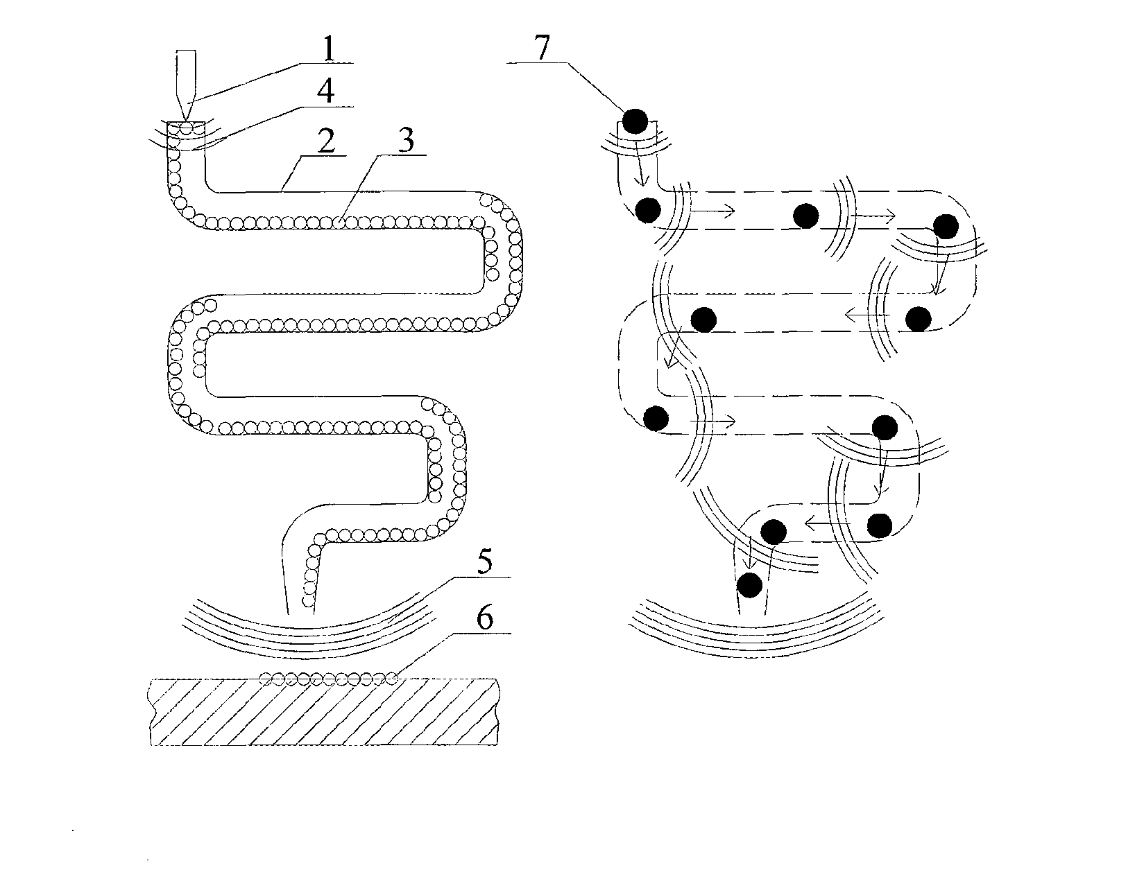
[0025]A pretreated 7050 aluminum alloy workpiece is fixed and clamped on the workpiece support plate 18; then, SiC nanopowders 22 are uniformly coated on a surface to be processed 15 of the 7050 aluminum alloy via the metal powder binder; the high pressure resistant glass pipe 21 is formed with a black paint strip on the inner wall and bottom of the upper opening, dried naturally and then clamped on the three-degree-of-freedom manipulator 9; the infrared locator 10 is turned on, and the manipulator is moved horizontally so that the infrared light irradiates on the black paint of the upper opening of the high pressure resistant glass pipe; then, the infrared locator is turned off, and the X / Y-axis workpiece support plate is moved so that the lower opening of the high pressure resistant glass pipe is aligned to a region to be processed; subsequently, the manipulator is moved vertically so that a distance from the lower opening to the surface to be processed is 10 mm; and finally, the ...

embodiment 2

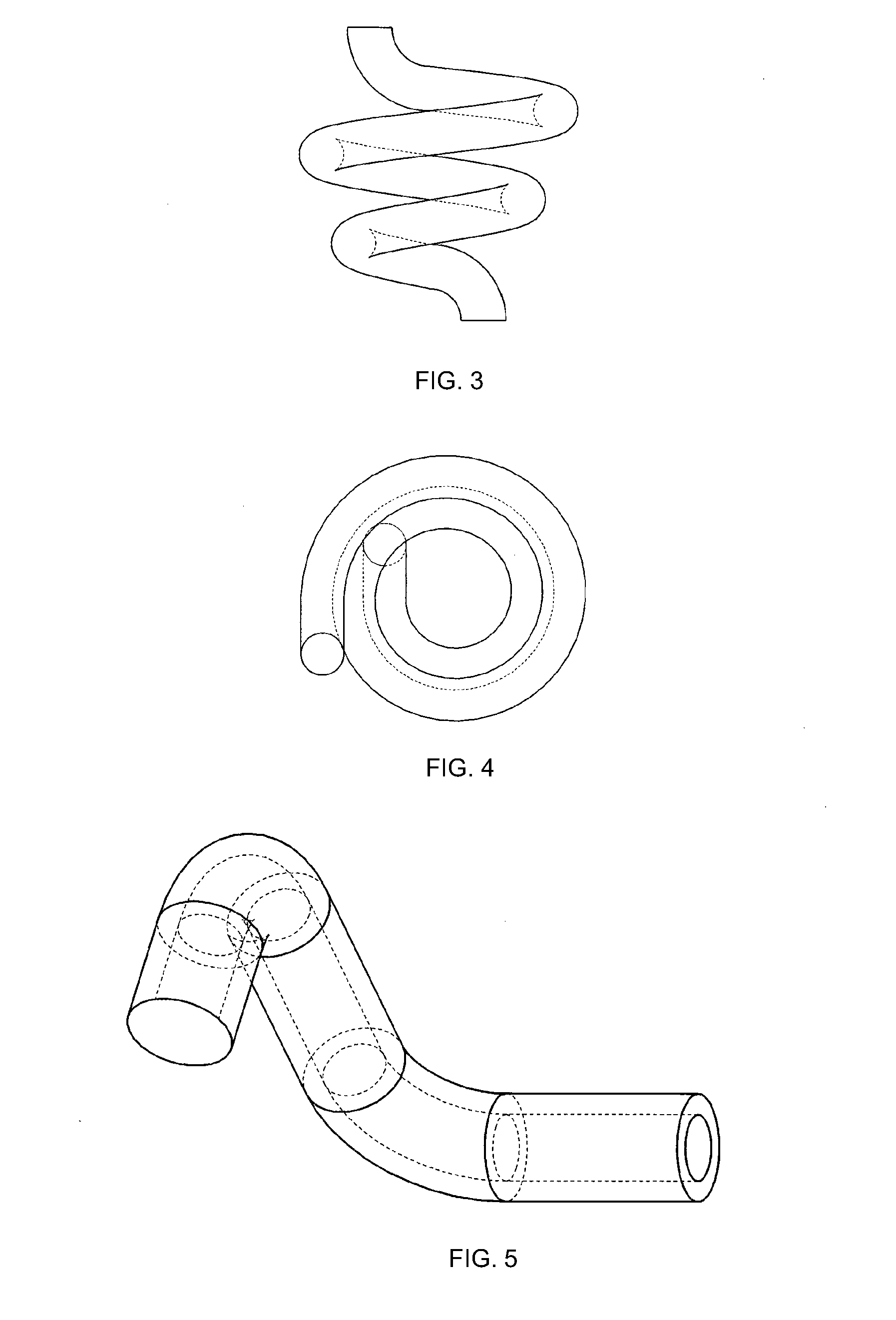
[0026]The high pressure resistant glass pipe for inducing a chain explosion may be in a spiral and inverted cone shape, as shown in FIG. 3 and FIG. 4. The pitch of the pipe is 20 mm. For the inner diameter of the spiral pipe, there may be a series of diameters (6 mm, 8 mm, 10 mm, etc.) depending on the laser spot. An upper end of the high pressure resistant glass pipe is closed, while a lower end thereof is open. The inner wall of the high pressure resistant glass pipe is a laser reflector and coated with the energy absorption material black paint. When a laser beam shocks the black paint at the upper opening, the black paint is vaporized and ionized to result in chain explosion in the pipe. The formed intense explosion wave is output from the lower opening to act on the surface to be processed of the workpiece.

embodiment 3

[0027]The high pressure resistant glass pipe for inducing a chain explosion shock wave may be in a shape as shown in FIG. 5. The high pressure resistant glass pipe can horizontally output a shock wave induced by a vertical laser beam and is used for processing a lateral surface of a blocky workpiece. The inner diameter of the pipe varies according to the diameter of the laser spot. The diameter at a switchback location is 15 mm. The inner wall of the pipe is a laser reflective mirror coated with an energy absorption material. One end of the pipe is open, while the other end thereof is closed. The closed end, coated with the energy absorption material on the inside, receives laser irradiation to generate a plasma. The energy absorption material at the switchback locations may absorb the residual laser beam for vaporization and ionization to generate a plasma, thereby providing intermediate energy support and shock wave support for the chain explosion.


PUM

PropertyMeasurementUnit
distanceaaaaaaaaaa
total lengthaaaaaaaaaa

Abstract

A method and apparatus for acquiring a nanostructured coating on a metal surface by using an intense shock wave generated by continuous explosion of a laser-induced plasma is provided. The method comprises: irradiating a laser beam on a black paint surface of an upper opening of a high pressure resistant glass pipe having a black paint strip arranged therein; the black paint absorbing the light energy and producing a plasma; generating an initial plasma explosion shock wave; transmitting the initial plasma explosion shock wave in the high pressure resistant glass pipe; generating a plasma cloud reaching a lower opening of a glass catheter; and, the shock wave pressure outputted embedding nanoparticles into a surface of a workpiece. The apparatus comprises the high pressure-resistant glass pipe with a zigzagging switchback shape or a spiral and inverted cone shape.

Description

FIELD OF TECHNOLOGY[0001]The following relates to the technical field of laser technology and surface strengthening, particularly to a method and apparatus for acquiring a nanostructured coating by effect of a laser-induced continuous explosion shock wave.BACKGROUND[0002]Various damages to materials are often resulted from, for example, corrosion, abrasion, oxidation, fatigue rupture and the like on the surface of the materials. The structure and characteristics of surface materials have a significant influence on the comprehensive performance of the materials. The preparation of a nanostructured surface with a certain thickness on the surface of materials may improve the overall mechanical property and service behavior in various environments of the materials. There are three major ways of acquiring a nanostructured surface on a metal surface: surface coating or deposition, surface self-nanocrystallization and hybrid nanocrystallization.[0003]Surface coating or deposition: the prep...

Claims


Application Information

Patent Timeline
Patent Type & Authority Applications(United States)
IPC IPC(8): B05D3/14
CPCB05D3/148C23C24/082C23C14/28
Inventor REN, XUDONGWANG, CHENGHUANGFU, YONGZHUOCHU, WEILI, YINGHONGHE, WEIFENGZHOU, XINRUAN, LIANGZHANG, YONGKANGDAI, FENGZEZHANG, TIAN
Owner JIANGSU UNIV
Why Eureka
Try Eureka