
Composite of metal and resin and method for manufacturing same

a technology of composites and metals, applied in the field of composites of metals and resins, can solve the problems of difficult to pull out the resin composition, the seed crystals cannot reach the farthest zones of the concave, etc., and achieve the effects of low resin strength of solidified resin, high production efficiency of composites, and low cos

Active Publication Date: 2014-07-03
TAISEI PLAS CO LTD
View PDF1 Cites 6 Cited by
  • Summary
  • Abstract
  • Description
  • Claims
  • Application Information

AI Technical Summary

Benefits of technology

The patent describes a method for joining a thermoplastic resin to a metal body using a metal surface layer with convexities and concavities and the presence of amine molecules. The resin needs to be a crystalline resin with high hardness and mechanical strength. When the resin comes into contact with a low-temperature mold or insert metal that is rapidly cooled, the resin can solidify inside the concavities on the metal surface, resulting in a strong joining (fixing) of the resin and metal. This method also provides a composite that exhibits excellent corrosion resistance, with a metal oxide, carbonate, or phosphate formed on the surface layer of the base material. By molding a thermoplastic resin composition containing PBT or PPS, the method allows for the production of composites with high mass production ability and productivity.

Problems solved by technology

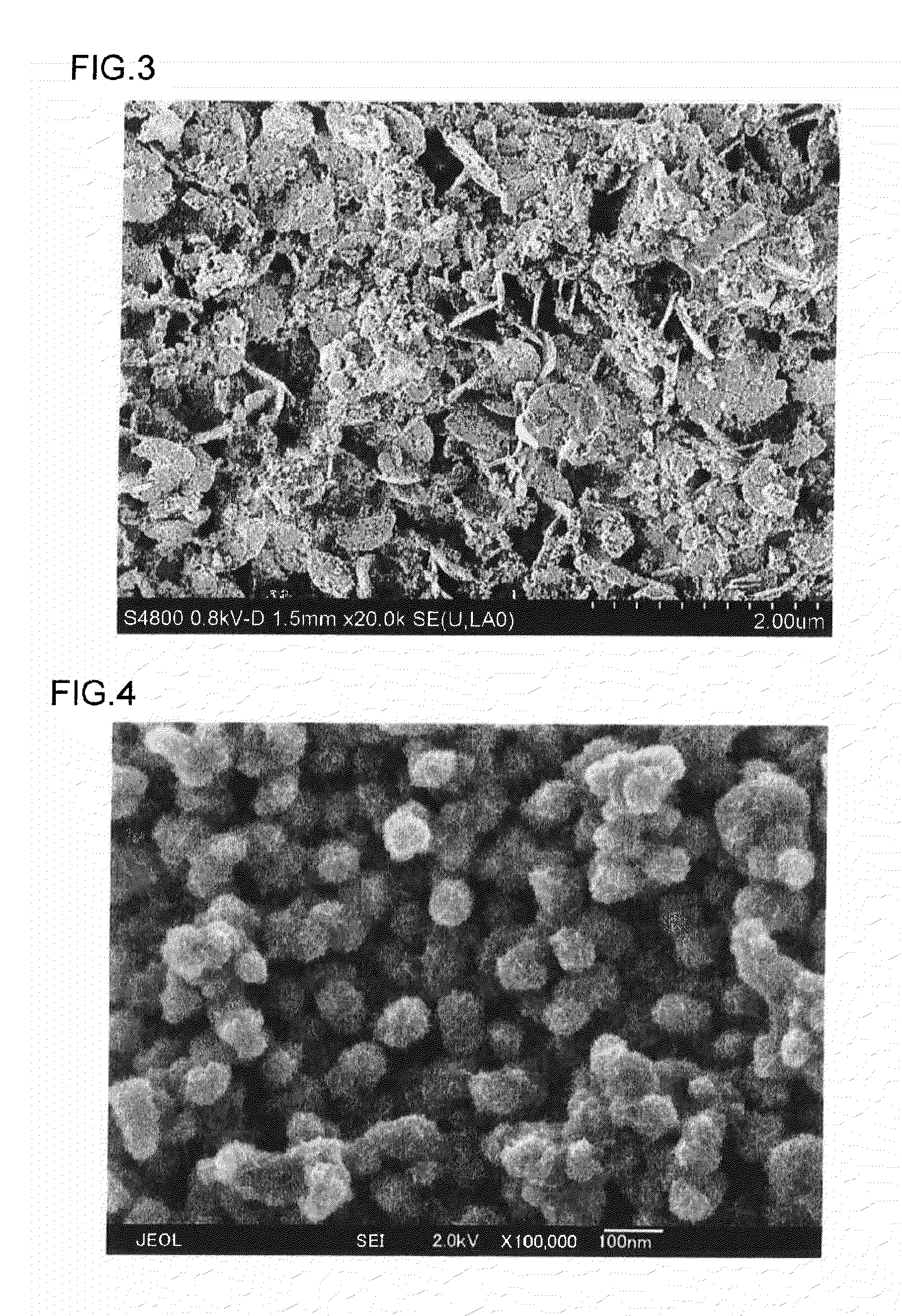
The minimum size of seed crystals, that is, the resin crystals, is about 10 nm or larger, and after the seed crystals have appeared and grown, even if they find their way to the entry of ultrafine concavities with a diameter of 20 to 80 nm, apparently it will not be easy for the seed crystals to reach the farthest zones of the concavities.
However, if a resin composition is employed in which seed crystals do not appear at once during rapid solidification and subsequent crystal growth is somewhat delayed, then the resin will be able to penetrate into concavities even when the diameter of concavities is several hundred nanometers.
Where the surface inside the concavities is rough, once the resin composition has crystallized and solidified inside the concavities, it will be difficult to pull the resin composition out, and in this case, an even stronger joint can be obtained.

Method used


Image

  • Composite of metal and resin and method for manufacturing same
  • Composite of metal and resin and method for manufacturing same
  • Composite of metal and resin and method for manufacturing same

Examples


preparation example 1

of PPS Composition

[0080]The PPS Preparation Example 1 represents a preparation example in which PPS and a polyolefin resin were mixed. A total of 6,214 g of Na2S.2.9H2O and 17,000 g of N-methyl-2-pyrrolidone were charged into an autoclave having a capacity of 50 L and equipped with a stirrer, and the temperature was gradually raised to 205° C., while stirring under a nitrogen flow, to distill off 1355 g of water. The system was cooled to 140° C., then 7160 g of p-dichlorobenzene and 5000 g of N-methyl-2-pyrrolidone were added and the system was sealed under a nitrogen flow. The temperature of the system was raised to 225° C. within 2 h, and the system was polymerized for 2 h at 225° C. Then, the temperature was raised to 250° C. within 30 min and the polymerization was further continued for 3 h at 250° C.

[0081]Upon completion of polymerization, the polymer cooled to room temperature was isolated with a centrifugal separation machine. The solid fraction of the polymer was repeatedly ...

preparation example 2

of PPS Composition

[0083]The PPS composition (1) obtained in the Preparation Example 1 of a PPS composition was cured for 3 h at a temperature of 250° C. under an oxygen atmosphere to obtain PPS (referred to hereinbelow as PPS (3)). The melt viscosity of the PPS (3) thus obtained was 1800 poise. A total of 5.98 kg of the PPS (3) obtained and 0.02 kg of polyethylene “Nipolon Hard 8300A (product name)” (manufactured by Tosoh Corp., Tokyo, Japan) were premixed homogeneously in a tumbler. Then, the mixture was melt kneaded at a cylinder temperature of 300° C. in the twin-screw extruder “TEM-35B” (above-mentioned), while supplying glass fibers “RES03-TP91” having an average fiber diameter of 9 μm and a fiber length of 3 mm from a side feeder so as to obtain a total added amount of 40 wt. %, thereby producing a pelletized PPS composition (2). This composition is a resin composition in which the polyolefin resin takes 0.3% of the entire resin fraction. The PPS composition (2) thus obtained ...

preparation example 3

of PPS Composition

[0084]A total of 7.2 kg of the PPS composition (2) obtained in the Preparation Example 1 of a PPS composition and 0.8 kg of glycidyl methacrylate-ethylene copolymer “Bondfast E” (manufactured by Sumitomo Chemical Co., Ltd.) were premixed homogeneously in a tumbler. Then, the mixture was melt kneaded at a cylinder temperature of 300° C. in the twin-screw extruder “TEM-35B” (above-mentioned), while supplying glass fibers “RES03-TP91” having an average fiber diameter of 9 μm and a fiber length of 3 mm from a side feeder so as to obtain a total added amount of 20 wt. %, thereby producing a pelletized PPS composition (3). This composition is a resin composition in which the polyolefin resin takes 10% of the entire resin fraction. The PPS composition (3) thus obtained was dried for 5 h at 175° C.


PUM

PropertyMeasurementUnit
diameteraaaaaaaaaa
lengthaaaaaaaaaa
diameteraaaaaaaaaa

Abstract

A magnesium alloy part is inserted into a mold, a resin composition is injected and joined to the part, and a composite is obtained. A part having, formed thereon, a surface layer of a metal oxide, a metal carbonate, or a metal phosphate in use of a usual conversion treatment or a modification method thereof can be used for the magnesium alloy plate 1. The surface that has a larger amount of crystal-like objects of a nanolevel on the surface layer composed of the metal oxide, metal carbonate, or metal phosphate has a higher level of hardness, microscopic roughness, and good injection joining force, and these parameters can be controlled by a conversion treatment method. A resin composition 4, containing PBT or PPS as the main component, is used as the resin composition part.

Description

CROSS-REFERENCE TO RELATED APPLICATION[0001]This application is a Divisional of copending U.S. application Ser. No. 12 / 089,097 filed Jun. 2, 2009, and wherein application Ser. No. 12 / 089,097 is a national stage application filed under 35 U.S.C. §371 of International Application No. PCT / JP2006 / 319864, filed on Oct. 4, 2006, which is based upon and claims priority under 35 U.S.C. §119(a) to Japan Patent Application Nos. 2005-290627 and 2006-145707 filed Oct. 4, 2005 and May 25, 2006, respectively.TECHNICAL FIELD[0002]The present invention relates to a composite of a metal and a resin that is composed of a metal and a resin composition suitable for casings of electronic devices, housings of home electric appliances, structural components, machinery parts, and the like, and also to a method for manufacturing the composite. More specifically, the present invention relates to a composite in which a base material made from a magnesium alloy that has been produced by various types of mechan...

Claims


Application Information

Patent Timeline
Patent Type & Authority Applications(United States)
IPC IPC(8): B32B27/06
CPCB32B27/06B29C45/14311B29C45/14778B29C2045/14237B29K2705/00B29K2705/02B32B15/08C23C22/05C23C22/18C23C22/57C23C22/83C23F1/22Y10T29/4998Y10T428/24355Y10T428/269Y10T428/31529Y10T428/31678Y10T428/31681B29C45/14B32B15/09C23C22/07
Inventor NARITOMI, MASANORIANDOH, NAOKIYAMANO, NAOKI
Owner TAISEI PLAS CO LTD
Learn More