
Chemical mechanical planarization conditioner

a technology of mechanical planarization and conditioner, which is applied in the direction of grinding drives, manufacturing tools, and abrasive surface conditioning devices, etc., can solve the problems of affecting the the impact on the polishing performance the deterioration of the polishing pad, so as to improve the cutting performance and longevity of the feature. , the effect of enhancing the longevity

Active Publication Date: 2014-04-24
ENTEGRIS INC
View PDF2 Cites 39 Cited by
  • Summary
  • Abstract
  • Description
  • Claims
  • Application Information

AI Technical Summary

Benefits of technology

The invention provides a pad conditioner that is machined from a substrate to have a desired distribution of feature heights and mesa roughness characteristics. This eliminates the problem of particles being dislodged from the pad conditioner. Instead, the protrusions on the surface of the pad conditioner provide geometric features that enhance its cutting performance and longevity. The machine process takes advantage of the porosity characteristics of the substrate material to achieve the desired distribution characteristics. The ceramic protrusions of the pad conditioner act as polymodal force concentrators, which can be formed in a repeatable pattern or of different heights. The use of smaller ceramic protrusions near the outside edge of the substrate reduces mechanical stress on the protrusions and enables the pad conditioner to ease into cutting of the polishing pad. The ceramic protrusions can be beta silicon carbide or silicon carbide.

Problems solved by technology

Over time, the polishing pad becomes matted and filled with debris from the CMP process.
CMP represents a major production cost in the manufacture of semiconductor and memory devices.
Additional cost for the CMP process includes tool downtime in order to replace the polishing pad and the cost of the test wafers to recalibrate the CMP polishing pad.
Over-texturing of the polishing pad results in a shortened life, while under-texturing results in insufficient material removal rate and lack of wafer uniformity during the CMP step.
However diamonds from these pad conditioners can become dislodged which can lead to yield loss due to scratching of the wafer during the polishing operation.

Method used


Image

  • Chemical mechanical planarization conditioner
  • Chemical mechanical planarization conditioner
  • Chemical mechanical planarization conditioner

Examples


Embodiment Construction

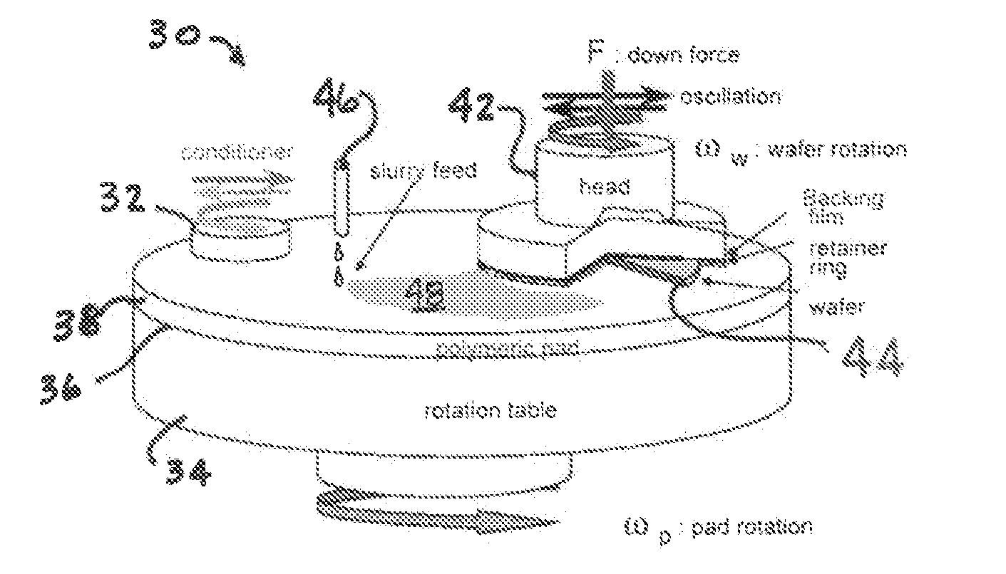
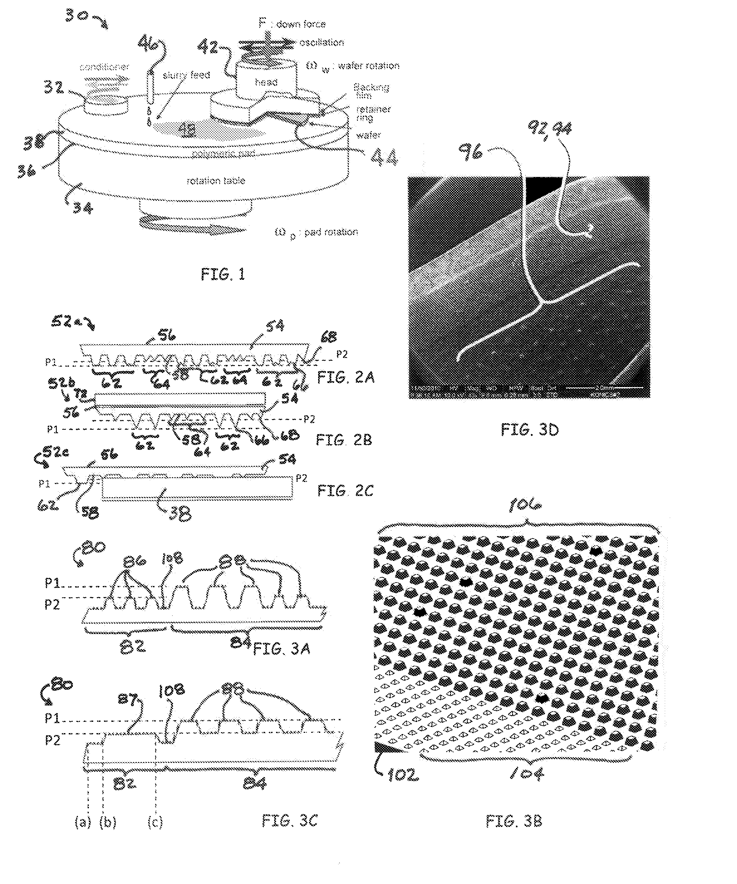
[0059]Referring now to FIG. 1, a wafer polishing apparatus 30 with a pad conditioner 32 in a chemical mechanical planarization (CMP) process is depicted in an embodiment of the invention. The depicted wafer polishing apparatus 30 includes a rotation table 34 having an upper face 36 with a CMP pad 38 (such as a polymeric pad) mounted thereon. A wafer head 42 having a wafer substrate 44 mounted thereon is arranged so that the wafer substrate 44 is in contact with the CMP pad 38. In one embodiment, a slurry feed device 46 provides an abrasive slurry 48 to the CMP pad 38.

[0060]In operation, the rotation table 34 is rotated so that the CMP pad 38 is rotated beneath the wafer head 42, pad conditioner 32 and slurry feed device 46. The wafer head 42 contacts the CMP pad 38 with a downward force F. The wafer head 42 can also be rotated and / or oscillated in a linear back-and-forth action to augment the polishing of the wafer substrate 44 mounted thereon. The pad conditioner 32 is also in cont...


PUM


Abstract

A pad conditioner for a CMP polishing pad is disclosed that includes a substrate that has a matrixical arrangement of protrusions that have a layer of poly crystalline diamond on at least their top surfaces. The protrusions may have varying shapes and elevations and may comprise a first set of protrusions and a second set of protrusions, the first set of protrusions have a first average height and the second set of protrusions have a second average height, the first average height different from the second average height, a top of each protrusion in the first set of protrusions has a non-flat surface and a top of each protrusion in the second set of protrusions has a non-flat surface.

Description

PRIORITY CLAIM[0001]The present application is a National Phase entry of PCT Application No. PCT / US2012 / 027916, filed Mar. 6, 2012, which claims priority to U.S. Provisional Patent Application No. 61 / 449,851, filed on Mar. 7, 2011, U.S. Provisional Patent Application No. 61 / 506,483, filed on Jul. 11, 2011 and U.S. Provisional Patent Application No. 61 / 513,294, filed on Jul. 29, 2011, the disclosures of which are hereby incorporated by reference in their entirety.FIELD OF THE INVENTION[0002]The disclosure is directed generally to semiconductor manufacturing equipment. More specifically, the disclosure is directed to conditioning devices for the cleaning of polishing pads used in the manufacture of semiconductors.BACKGROUND[0003]Chemical mechanical planarization (CMP) is used extensively in the manufacture of semiconductor chips and memory devices. During a CMP process, material is removed from a wafer substrate by the action of a polishing pad, a polishing slurry, and optionally chem...

Claims


Application Information

Patent Timeline
Patent Type & Authority Applications(United States)
IPC IPC(8): B24B53/017
CPCB24B53/017H01L21/304
Inventor SMITH, JOSEPHGALPIN, ANDREWWARGO, CHRISTOPHER
Owner ENTEGRIS INC
Learn More