Motor driving control apparatus
- Summary
- Abstract
- Description
- Claims
- Application Information
AI Technical Summary
Benefits of technology
Problems solved by technology
Method used
Image
Examples
first embodiment
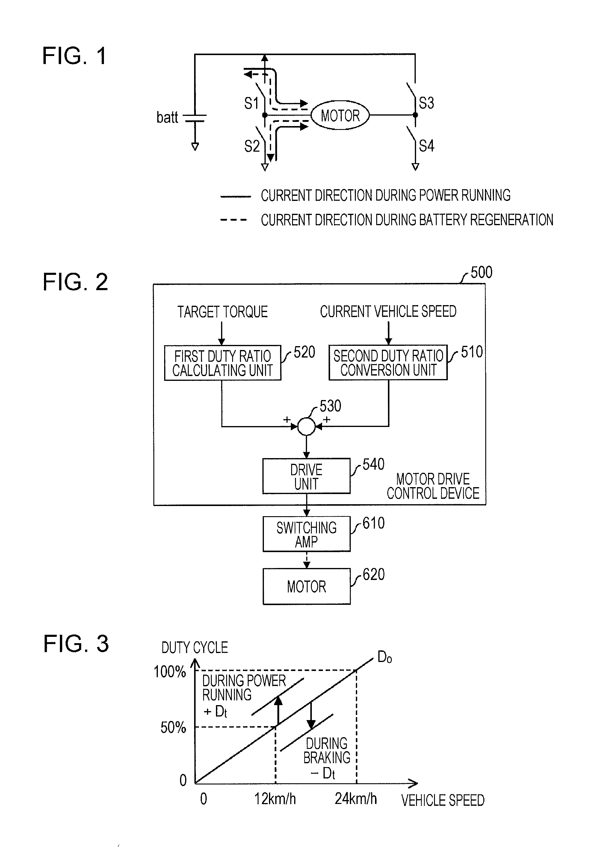
[0070]FIG. 2 is a functional block diagram of a motor drive control device 500 related to the present embodiment. The motor drive control device 500 includes a first duty cycle conversion unit 520, a second duty cycle conversion unit 510, an adding unit 530, and a drive unit 540. The output of the drive unit 540 of the motor drive control device 500 is connected to a complementary type switching amplifier 610, and a motor 620 is driven by this switching amplifier 610.
[0071]For example, a first digital value corresponding to the current speed from a sensor connected to the applicable the motor drive control device 500 and a third digital value corresponding to a target torque from an instruction mechanism or sensor connected to the motor drive control device 500 is input into the motor drive control device 500, and so processing is performed there. Also, the second duty cycle conversion unit 510 executes processing to multiply the conversion coefficient with the first digital value (...
second embodiment
[0078]Regarding the first Embodiment, there is no problem when obtaining the output torque corresponding to the target torque, but current flowing to the motor could increase due to variances in components and such, and as a result, this can cause a torque larger than the target torque to be produced.
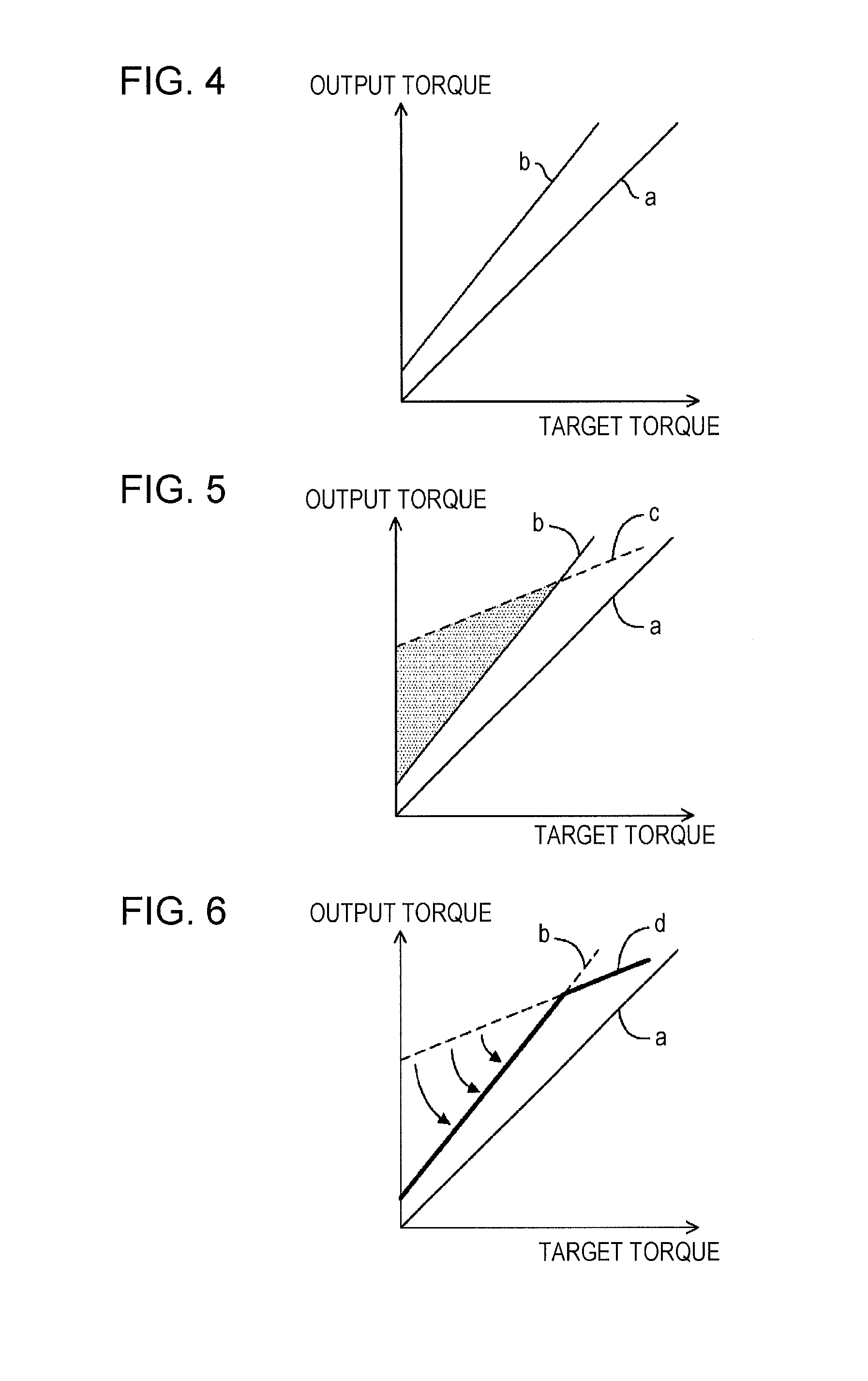
[0079]As illustrated in FIG. 4, it is generally preferable if the output torque corresponding to the target torque matches as illustrated by the straight line a. Also, for safety reasons, the output torque should be set corresponding to the target torque, and also should be set to a value in the region below the upper limit of the allowable amount as illustrated by the straight line b. However, as indicated by the dotted line c illustrated in FIG. 5, if the current flowing to the motor is increased for some reason, a larger current than that corresponding to the target torque flows, and as a result, there may be cases in which an output torque in a region (shaded area) over the upper li...
third embodiment
[0093]The third Embodiment of the present invention will be described using FIG. 8 through FIG. 27. Here, this will be described using an example of a so-called electrically assisted bicycle in which the motor is installed on a bicycle.
[0094]FIG. 8 is an external view illustrating an example of an electrically assisted bicycle related to the third Embodiment. The electrically assisted bicycle 1 is typical rear wheel drive type with a crankshaft and a rear wheel connected by a chain, and has a motor drive device installed. The motor drive device includes a secondary battery 101, a motor drive control mechanism 102, a torque sensor 103, a brake sensor 104, a motor 105, and an operation panel 106.
[0095]The secondary battery 101 may be, for example, a lithium ion secondary battery with a maximum supply voltage of 24 V (when fully charged), but other types of batteries such as a lithium ion polymer secondary battery, or a nickel hydride chargeable battery may be used.
[0096]The torque sen...
PUM
 Abstract
Description
Claims
Application Information
 - R&D
- Intellectual Property
- Life Sciences
- Materials
- Tech Scout
- Unparalleled Data Quality
- Higher Quality Content
- 60% Fewer Hallucinations
Browse by: Latest US Patents, China's latest patents, Technical Efficacy Thesaurus, Application Domain, Technology Topic, Popular Technical Reports.
© 2025 PatSnap. All rights reserved.Legal|Privacy policy|Modern Slavery Act Transparency Statement|Sitemap|About US| Contact US: help@patsnap.com


