
Dual source system and method

Active Publication Date: 2014-01-23
SCIAPS
View PDF21 Cites 25 Cited by
  • Summary
  • Abstract
  • Description
  • Claims
  • Application Information

AI Technical Summary

Benefits of technology

The patent describes a new tool that combines two technologies to measure elements and compounds in a sample. This device is small and portable, making it easy to carry around. By measuring the elements in the sample using one technology, the system can better identify and quantify the compounds present. This knowledge also helps in analyzing the data collected from the sample more accurately. Overall, this device allows for a more comprehensive and precise analysis of samples.

Problems solved by technology

X-rays, however, pose a safety concern.
Also, portable and benchtop XRF analyzers have not to date been used to determine lower atomic number elements such as beryllium, sodium, carbon, magnesium, and the like.
Portable Raman and NIR analyzers are able to identify compounds present in a mixture, but they are generally limited to identifying what main compounds are present (as opposed to how much of each compound is present), or, at best, they can provide an approximate quantification of only a few components in a mixture of compounds.
This limitation is due to sample response variation as a function of particle size, particle density, and mixture type, whether it be a solid solution or an inhomogeneous mixture of compounds.
In addition, both the Raman and NIR methods are sensitive to material very near the sample surface so that any variation is bulk vs. surface concentrations will be missed.
In addition, currently available portable Raman and NIR units typically require a good deal of spectral interpretation from the operator, thus limiting user community to more technical users.
Still, LIBS spectroscopy, for example, can produce inaccurate elemental concentrations in some cases and Raman and NIR spectroscopy can report one or more inaccurate compositions, mainly because for many compounds, the Raman or NIR spectra produced by those compounds are very similar.
Fusing the data may not improve accuracy.

Method used


Image

  • Dual source system and method
  • Dual source system and method
  • Dual source system and method

Examples


Embodiment Construction

[0024]Aside from the preferred embodiment or embodiments disclosed below, this invention is capable of other embodiments and of being practiced or being carried out in various ways. Thus, it is to be understood that the invention is not limited in its application to the details of construction and the arrangements of components set forth in the following description or illustrated in the drawings. If only one embodiment is described herein, the claims hereof are not to be limited to that embodiment. Moreover, the claims hereof are not to be read restrictively unless there is clear and convincing evidence manifesting a certain exclusion, restriction, or disclaimer.

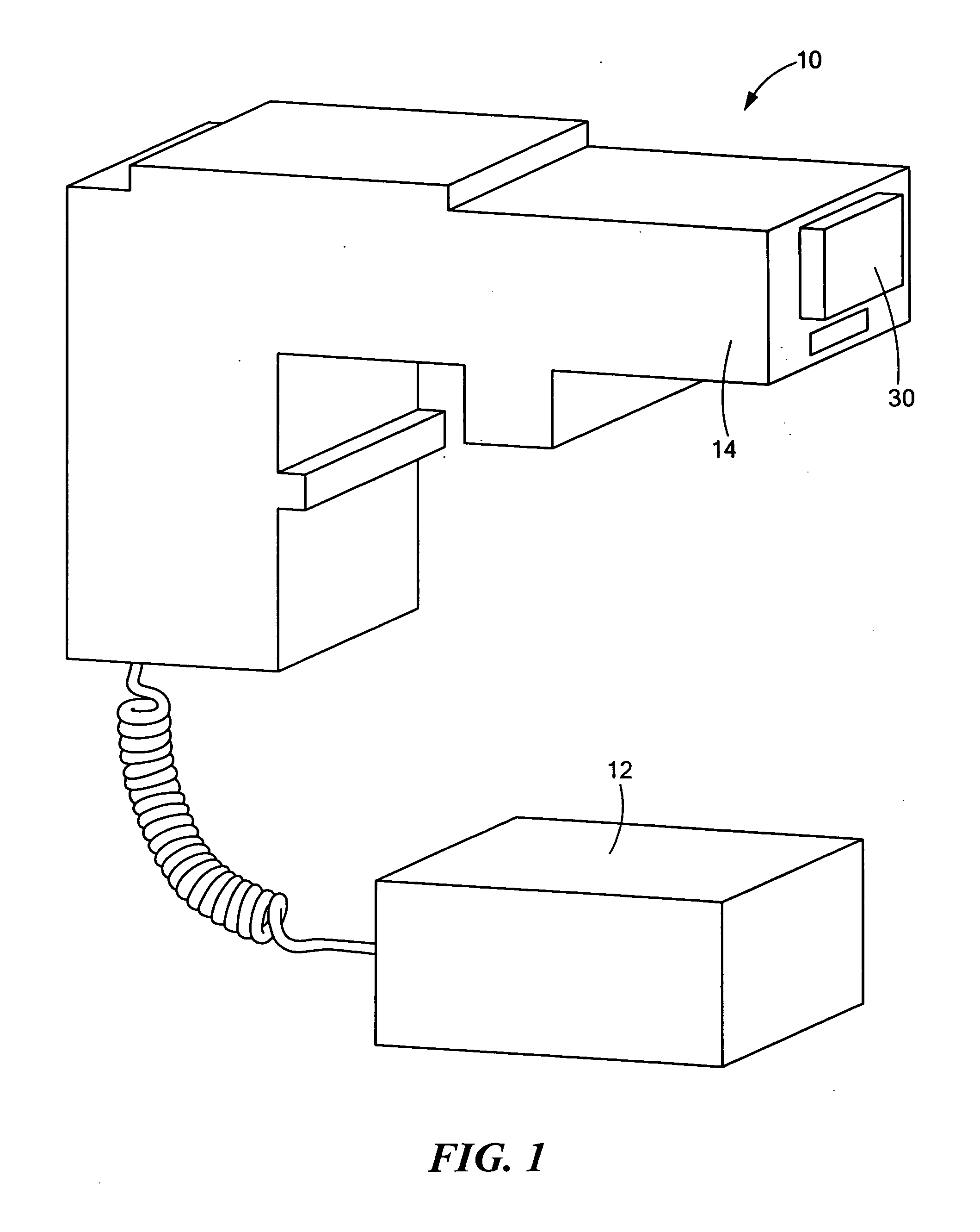
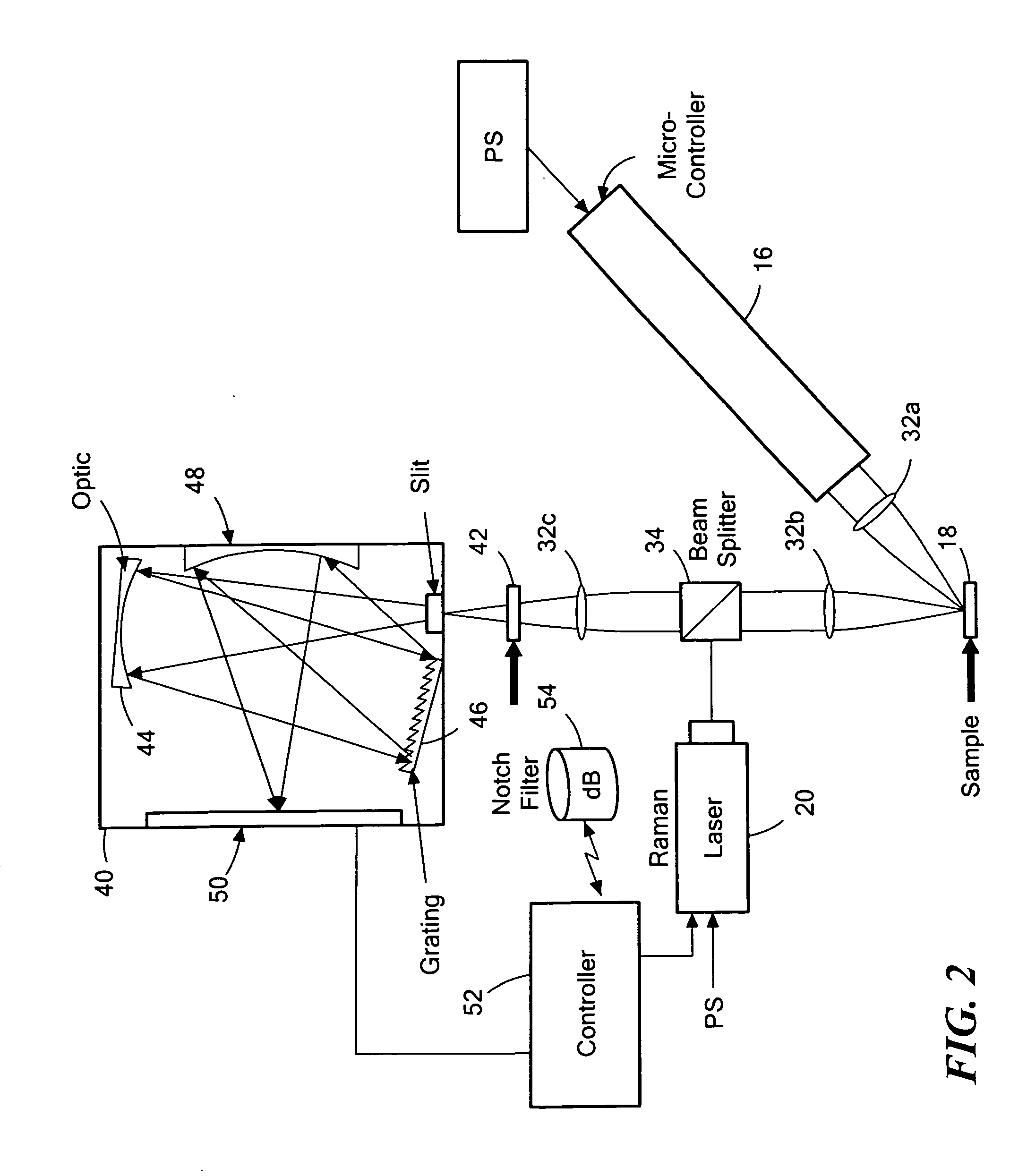
[0025]FIG. 1 shows a version of a portable, hand held dual source device 10 embodying an example of the invention. In one design, device 10 may include separate belt or shoulder mounted power pack 12. Housing 14 typically houses a high power laser 16, FIG. 2 used in a LIBS analysis to determine elemental concentration in sa...


PUM


Abstract

A dual source system and method includes a high power laser used to determine elemental concentrations in a sample and a lower power device used to determine compounds present in the sample. A detector subsystem receives photons from the sample after laser energy from the high power laser strikes the sample and provides a first signal. The detector subsystem then receives photons from the sample after energy from the lower power device strikes the sample and provides a second signal. The high power laser is pulsed and the first signal is processed to determine elemental concentrations present in the sample. The lower power device is energized and the second signal is processed to determine compounds present in the signal. Based on the elemental concentrations and the compounds present, the compounds present in the sample are quantified.

Description

FIELD OF THE INVENTION[0001]The subject invention relates to spectroscopic instruments.BACKGROUND OF THE INVENTION[0002]Spectroscopic instruments are fairly well known. X-ray based instruments, for example, can be used to determine the elemental make up of a sample using x-ray fluorescence spectroscopy. Portable XRF has become a preferred technique for elemental analysis in the field. Portable XRF is fast, non-destructive, and provides reasonably accurate results (i.e., quantification of elemental concentrations in a wide variety of samples). With XRF, an x-ray tube is used to direct x-rays at a sample. Atoms in the sample absorb x-rays and re-emit x-rays that are unique to the atomic structure of a given element. A detector measures the energy of each x-ray and counts the total number of x-rays produced at a given energy. From this information, the types of elements and the concentration of each element can be deduced. Commercially available analyzers include the Delta manufactured...

Claims


Application Information

Patent Timeline
IPC IPC(8): G01J3/42G01J3/44
CPCG01J3/44G01J3/0208G01J3/0227G01J3/18G01J3/2803G01J3/443G01N21/359G01N21/65G01N21/718G01N2201/0221
Inventor SACKETT, DON
Owner SCIAPS
Learn More