Inductively coupled plasma source with multiple dielectric windows and window-supporting structure

Active Publication Date: 2014-01-23
APPLIED MATERIALS INC
View PDF13 Cites 16 Cited by
  • Summary
  • Abstract
  • Description
  • Claims
  • Application Information

AI Technical Summary

Benefits of technology

The plasma reactor described in this patent has a unique design that allows for improved plasma processing. It includes a cylindrical enclosure with a metallic portion and a dielectric window, and multiple concentric coil antennas. The reactor also includes a center gas disperser, a top gas plate, and a heater layer. The design of the reactor allows for better control of the plasma processing and improved uniformity of the plasma. The reactor can also include a side air flow passage and a bottom air flow passage for better air flow management. The technical effects of this design include improved plasma processing, better control of plasma processing, and improved uniformity of plasma processing.

Problems solved by technology

Such uniformity is becoming more difficult to achieve, as substrate size is increasing and device geometry is shrinking.
As workpiece diameter and chamber diameter increase, we have found this approach is not adequate, as the larger size increases the difficultly of attaining the requisite process uniformity.

Method used


Image

  • Inductively coupled plasma source with multiple dielectric windows and window-supporting structure
  • Inductively coupled plasma source with multiple dielectric windows and window-supporting structure
  • Inductively coupled plasma source with multiple dielectric windows and window-supporting structure

Examples


Embodiment Construction

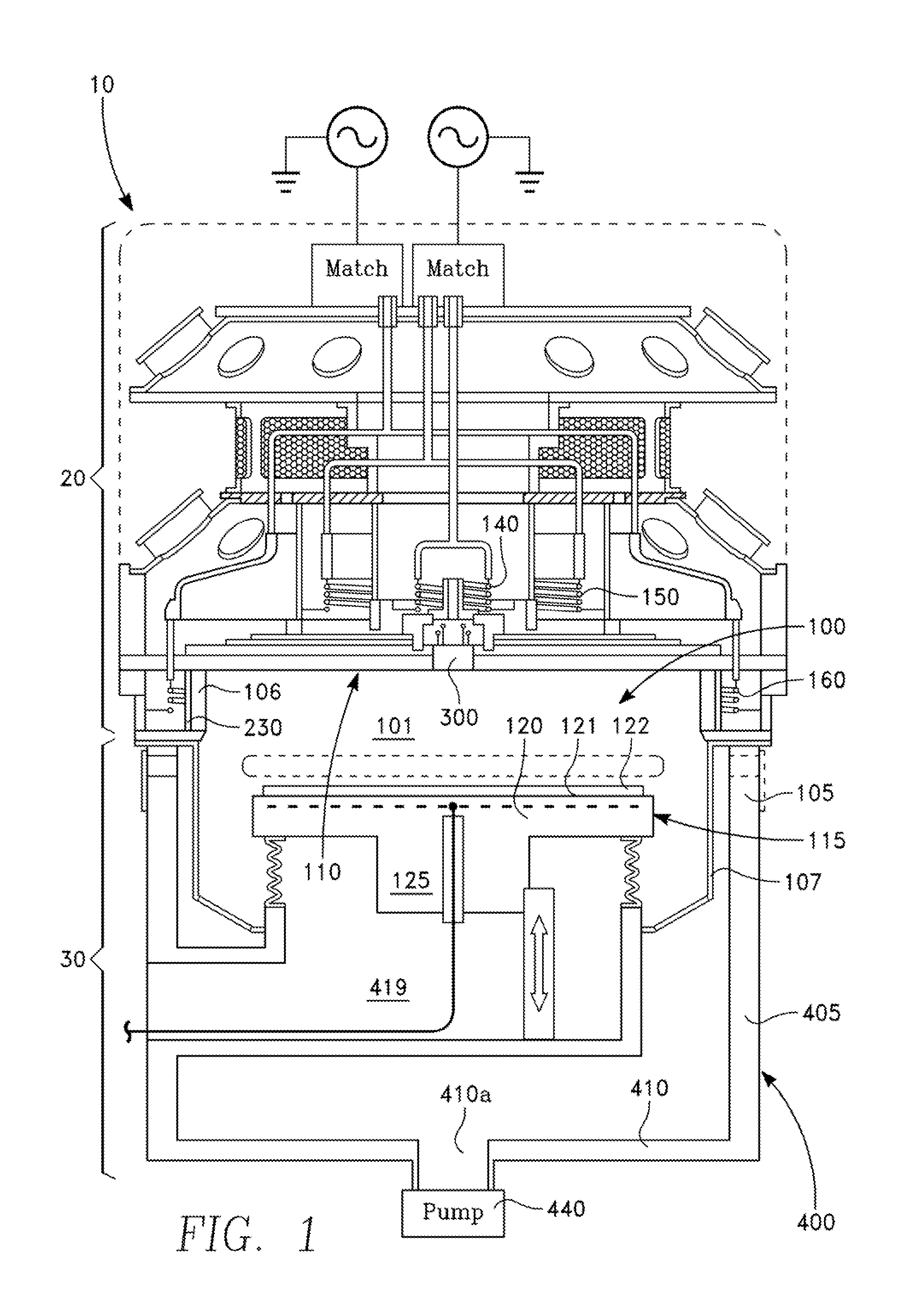
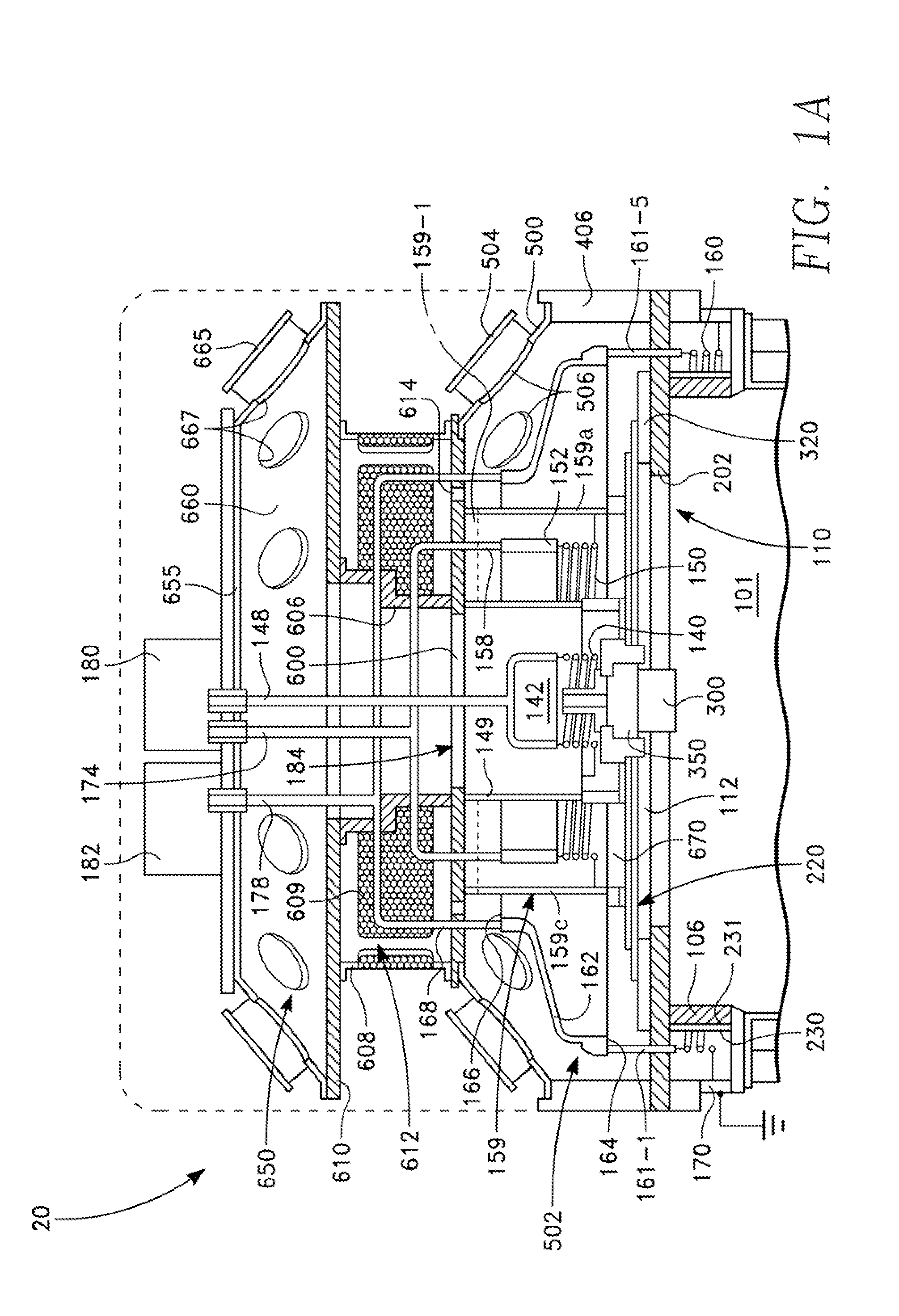
[0048]A plasma reactor 10 depicted in FIG. 1 includes an upper portion 20 depicted in the enlarged view of FIG. 1A and a lower portion 30 depicted in the enlarged view of FIG. IB. Referring to FIGS. 1, 1A and 1B, the plasma reactor 10 includes a plasma processing chamber 100 having a side wall 105 and a lid assembly 110. The side wall 105 has an axially symmetrical shape, such as a cylinder. The side wall 105 includes an axially symmetrical (e.g., cylindrical) dielectric side window 106 and a chamber liner 107, which may be formed of metal. A workpiece support 115 inside the chamber 100 includes a pedestal 120 having a workpiece support surface 121 facing the lid assembly 110 for holding a workpiece 122, and a post 125 supporting the pedestal 120. A processing region 101 of the chamber 100 is confined by the lid assembly 110, the pedestal 120 and the side wall 105. The pedestal 120 may include an insulated internal electrode 130. Optionally, an electrostatic chucking (ESC) voltage a...


PUM

PropertyMeasurementUnit
Lengthaaaaaaaaaa
Dielectric polarization enthalpyaaaaaaaaaa
Diameteraaaaaaaaaa

Abstract

A plasma reactor enclosure has a metallic portion and a dielectric portion of plural dielectric windows supported on the metallic portion, each of the dielectric windows extending around an axis of symmetry. Plural concentric coil antennas are disposed on an external side of the enclosure, respective ones of the coil antennas facing respective ones of the dielectric windows.

Description

CROSS-REFERENCE TO RELATED APPLICATION[0001]This application claims the benefit of U.S. Provisional Application Ser. No. 61 / 673,937, filed Jul. 20, 2012 entitled SYMMETRICAL MULTIPLE COAXIAL ICP SOURCE AND SYMMETRICAL FLOW CHAMBER, by Andrew Nguyen, et al.BACKGROUND[0002]1. Field[0003]Embodiments of the present invention are generally concerned with a plasma processing reactor chamber for processing workplaces, in which plasma is generated by inductive coupling of RF power to process gases inside the chamber.[0004]2. Description of the Related Art[0005]Electronic devices such as integrated circuits, flat panel displays and the like, are fabricated by a series of processes, in which thin film layers are deposited on substrates and etched into desired patterns. The process steps may include plasma-enhanced reactive ion etching (RIE), plasma-enhanced chemical vapor deposition (CVD), plasma-enhanced physical vapor deposition (PVD).[0006]Uniform distribution of etch rate or deposition ra...

Claims


Application Information

Patent Timeline
IPC IPC(8): B01J12/00
CPCB01J12/002H01J37/3211H01J37/32733H01J37/32834H01J37/321C23C14/28C23F1/08H05H1/46H01J37/3244
Inventor NGUYEN, ANDREWCOLLINS, KENNETH S.RAMASWAMY, KARTIKRAUF, SHAHIDCARDUCCI, JAMES D.BUCHBERGER, JR., DOUGLAS A.AGARWAL, ANKURKENNEY, JASON A.DORF, LEONIDBALAKRISHNA, AJITFOVELL, RICHARD
Owner APPLIED MATERIALS INC
Why Eureka
Try Eureka