Eureka AIR delivers breakthrough ideas for toughest innovation challenges, trusted by R&D personnel around the world.

Electrolytes including fluorinated solvents for use in electrochemical cells

Inactive Publication Date: 2013-12-19
A123 SYSTEMS LLC
View PDF4 Cites 36 Cited by
  • Summary
  • Abstract
  • Description
  • Claims
  • Application Information

AI Technical Summary

Benefits of technology

The patent text describes electrochemical cells and electrolytes used to build these cells. The electrolytes contain ion-supplying salts and fluorinated solvents capable of maintaining single phase solutions with the salts. The use of fluorinated solvents increases safety characteristics of the cells. The amount of fluorinated solvents in the electrolytes can range between about 30% and 80% by weight. Fluorinated salts can also be used in the electrolytes. The electrolyte may also contain a flame retardant, such as phosphazene or ionic liquids. The technical effects of this patent text include improved safety and efficiency of electrochemical cells.

Problems solved by technology

However, electrolytes containing large amounts (e.g., greater than 80% by weight excluding the weight of the salt) of carbonate based solvents have poor chemical stability and safety.
Electrochemical cells built with these electrolytes can easily catch fire during various safety tests, such as overcharge, heating, nail penetration, and other tests.
Such poor safety performance limits uses of electrochemical cells for some critical applications, such as aerospace, medical devices, and the like.
However, non-flammable liquids (e.g., solvents) typically have small dipole moments and low dielectric constants resulting in poor solubility of electrolyte salts.
Furthermore, it may be difficult to combine various non-flammable liquids with other liquids that have larger dipole moments resulting in separation of these liquids into two phases, i.e., one phase containing a low-dipole moment non-flammable liquid and another phase containing a high-dipole moment liquid.
Higher concentrations of the flame retardant additives may be desirable from the safety perspectives but may have negative impacts on cycling performance of a cell.
Hydrofluoric acid can be damaging to various cell components.
At lower concentrations, the salts may not supply adequate amount of ions, while higher concentrations are generally limited by solubility limits and other considerations.
It has been found that salts with smaller anions tend to have more difficulties in dissolving in these electrolytes.
However, these salts are generally used for less concentrated solutions and may result in high viscosity solutions that limit the electrolyte transport properties.
For comparison, many conventional electrolyte solvents have relatively low flashpoints (e.g., dimethyl carbonate has a flashpoint of 14° C. while ethyl methyl carbonate has a flashpoint of 23° C., and diethyl carbonate has a flashpoint of 25° C.) resulting in high flammability of these solvents and electrolytes formed by these solvents.
However, the lower molecular weight esters are more volatile and reactive than the higher molecular weight esters.
Higher concentrations of the flame-retardant additive may negatively impact on the cell performance (e.g., cycle life), while lower concentrations may be ineffective.
Less conductive electrolyte may not be suitable for some battery applications, in particular high rate applications.
It is both inexpensive and has high stability and safety, because the relatively strong phosphate bonds tend to keep the oxygen in the lattice during overcharge, but has poor conductance and require substantial amounts of conductive additives, LiMXM″1-XPO4 where M′ and M″ are different metals (e.g. LiFePO4), LiFeXM1-XPO4, where M is a metal, LiVOPO4, Li3V2(PO4)3, LiMPO4, where M is a metal such as iron or vanadium.
The decline in performance was attributed to an increased viscosity, which reduces mobility of lithium ions within the cells.

Method used


Image

  • Electrolytes including fluorinated solvents for use in electrochemical cells
  • Electrolytes including fluorinated solvents for use in electrochemical cells
  • Electrolytes including fluorinated solvents for use in electrochemical cells

Examples


case 102

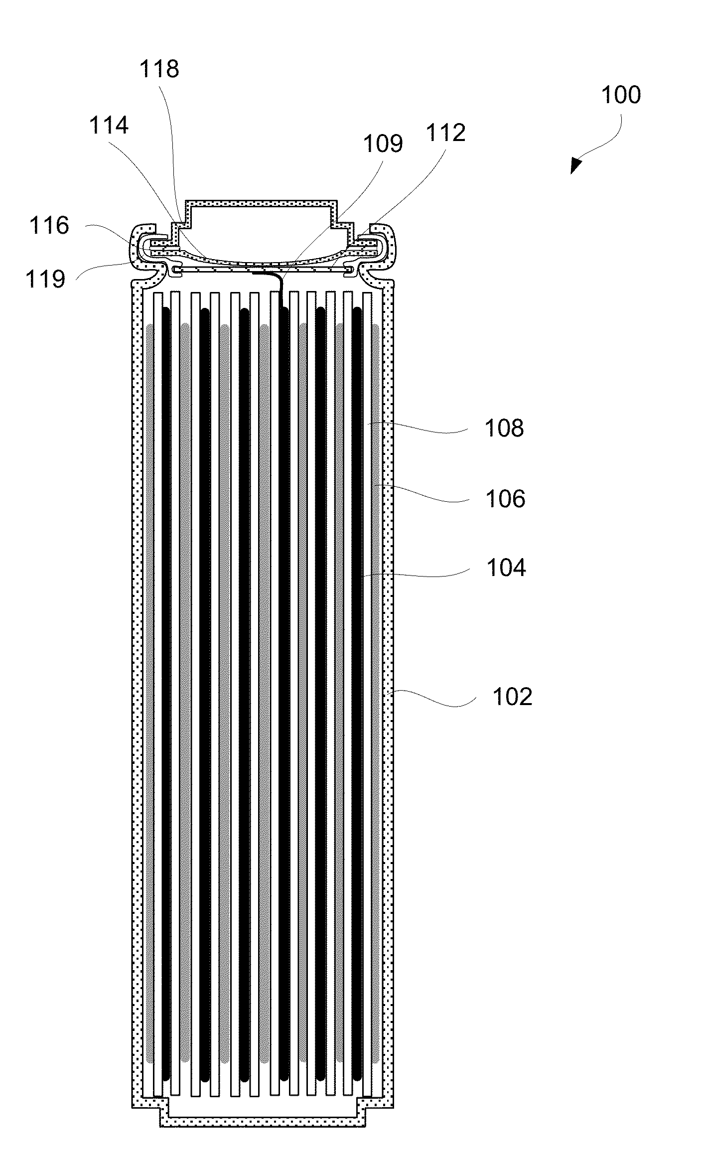
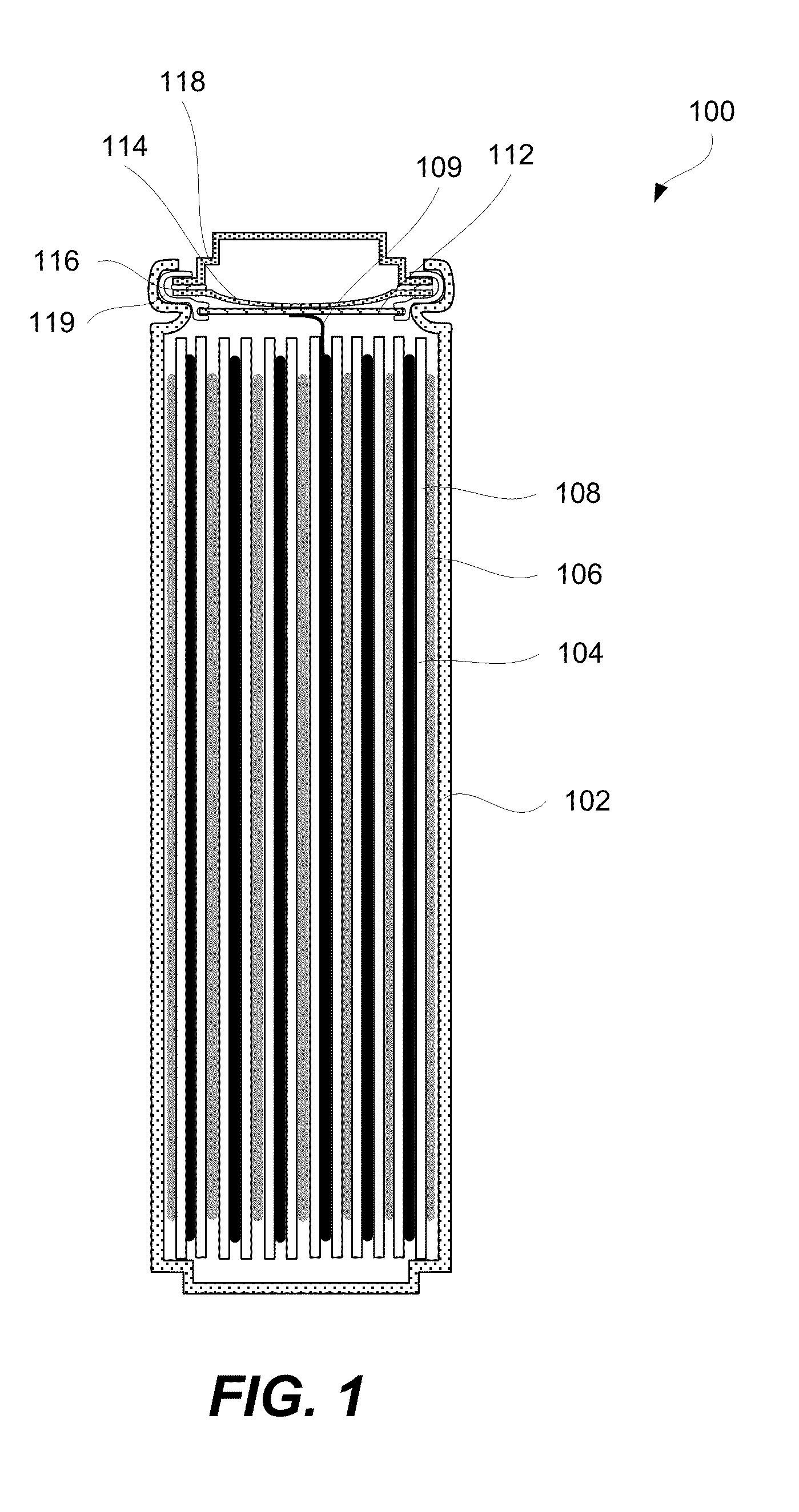
[0077]Case 102 may be rigid, in particular for lithium ion cells. Other types of cells may be packed into a flexible, foil-type (polymer laminate) case. For example, pouch cells are typically packed into a flexible case. A variety of materials can be chosen for case 102. Selection of these materials depends in part on an electrochemical potential to which case 102 is exposed to. More specifically, the selection depends on which electrode, if any, case 102 is connected to and what are operating potentials of this electrode.

[0078]If case 102 is connected to positive electrode 106 of a lithium ion battery, then case 102 may be formed from titanium 6-4, other titanium alloys, aluminum, aluminum alloys, and 300-series stainless steel. On the other hand, if case 102 is connected to negative electrode 104 of the lithium ion battery, then case 102 may be made from titanium, titanium alloys, copper, nickel, lead, and stainless steels. In some embodiments, case 102 is neutral and may be conne...


PUM


Abstract

Provided are electrochemical cells and electrolytes used to build such cells. The electrolytes include ion-supplying salts and fluorinated solvents capable of maintaining single phase solutions with the salts at between about −30° C. to about 80° C. The fluorinated solvents, such as fluorinated carbonates, fluorinated esters, and fluorinated esters, are less flammable than their non-fluorinated counterparts and increase safety characteristics of cells containing these solvents. The amount of fluorinated solvents in electrolytes may be between about 30% and 80% by weight not accounting weight of the salts. Fluorinated salts, such as fluoroalkyl-substituted LiPF6, fluoroalkyl-substituted LiBF4 salts, linear and cyclic imide salts as well as methide salts including fluorinated alkyl groups, may be used due to their solubility in the fluorinated solvents. In some embodiments, the electrolyte may also include a flame retardant, such as a phosphazene or, more specifically, a cyclic phosphazene and / or one or more ionic liquids.

Description

CROSS-REFERENCE TO RELATED APPLICATIONS[0001]This application claims the benefit under 35 U.S.C. §119(e) of U.S. Provisional Patent Application 61 / 690,155, entitled: “ELECTROCHEMICAL CELLS AND RELATED COMPOUNDS” filed on Jun. 19, 2012 (Attorney Docket No. LE-001.01), which is incorporated herein by reference in its entirety.GOVERNMENT LICENSE RIGHTS[0002]This invention was made with government support under DE-SC0005117 awarded by the Department of Energy. The government has certain rights in the invention.BACKGROUND[0003]Significant work has been directed to the performance improvement of electrochemical cells. Specifically, safety, overall capacity, cycle life, and operation conditions of the cells have been considered and extensively studied. Improving some of these characteristics often results in deteriorating other ones. For example, increase in capacity and charge-discharge rates may deteriorate safety performance. Selection of electrolytes or, more specifically, various elec...

Claims


Application Information

Patent Timeline
IPC IPC(8): H01M10/0569H01M10/0525
CPCH01M10/0569H01M10/0525H01M10/052H01M10/0563H01M10/0567H01M10/0568H01M2300/0034H01M2300/0037Y02E60/10
Inventor TIKHONOV, KONSTANTINYIP, KA KILIN, TZU-YUAN
Owner A123 SYSTEMS LLC
Why Eureka
Eureka Blog
Learn More