Eureka AIR delivers breakthrough ideas for toughest innovation challenges, trusted by R&D personnel around the world.

Solid state light source for photocuring

a light source and photocuring technology, applied in the field of solid-state light sources for photocuring, can solve the problems of reducing the life of the lamp, reducing the life span of the lamp, and requiring costly replacement parts, and achieves the effects of low heat output, reduced cost, and superior performance and cost analysis

Active Publication Date: 2013-12-19
LUMENCOR
View PDF7 Cites 7 Cited by
  • Summary
  • Abstract
  • Description
  • Claims
  • Application Information

AI Technical Summary

Benefits of technology

The present invention is a LED light engine system that is suitable for photocuring. It is small, durable, and affordable. The system provides high-intensity light across a range of wavelengths using a single component. It has comparable performance and is more stable and reliable than traditional optical subsystems. The LED light engine requires less power and has no moving parts, making it ideal for photocuring applications. Additionally, an improved cooling system is provided to prevent contamination from cooling airflow. Overall, the LED light engine system is a compact, effective, and cost-efficient solution for photocuring.

Problems solved by technology

However, QTH and arc lamps also emit a great deal of heat / infrared.
The large heat output however requires the QTH and arc lamp systems to have substantial thermal management systems and also reduces the life span of the lamps such that costly replacement parts are required.
This further reduces the effective lifespan of the lights.
However, the emission spectra of the Argon laser is very narrow and may not be compatible with some photocurable resins.
Moreover, Argon laser systems are expensive and have significant thermal regulation requirements
However LEDs presents trade-offs with respect to emission wavelength dependent intensity, broad emission spectrum (spectral half width on the order of 30 nm or more), poor spectral stability, and the wide angular range of emission.
The narrow band emission may not be compatible with some photocurable resins.
In addition, the process used to manufacture LED's cannot tightly control their spectral stability; anyone wishing to use LED's in applications requiring a good spectral stability typically works directly with a supplier to essentially hand-pick the LED's for the particular application.
While optics can narrow the emission band and focus the light output, the resulting loss in power and increase in thermal output further complicates the use of LEDs for photocuring.
Thus, it can be difficult to provide sufficient light at a wavelength suitable for exciting a particular photoinitiator.
While lighting manufacturers cannot provide all things to all applications, it is precisely this breadth of demand for which a light engine can be designed.
Accordingly, it may be difficult to ensure sufficient light energy is provided at a wavelength suitable for exciting the photoinitiator.
Without proper absorption, free radical polymerization may not occur uniformly throughout the resin.
Moreover, where narrow band light sources, such as LEDs, are used the wavelength provided will not be suitable for exciting all photoinitiators in all compositions and manufacturing environments.

Method used


Image

  • Solid state light source for photocuring
  • Solid state light source for photocuring
  • Solid state light source for photocuring

Examples


Embodiment Construction

LED Light Engine System for Photocuring

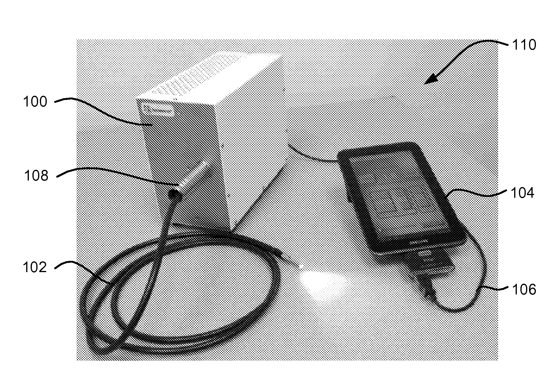
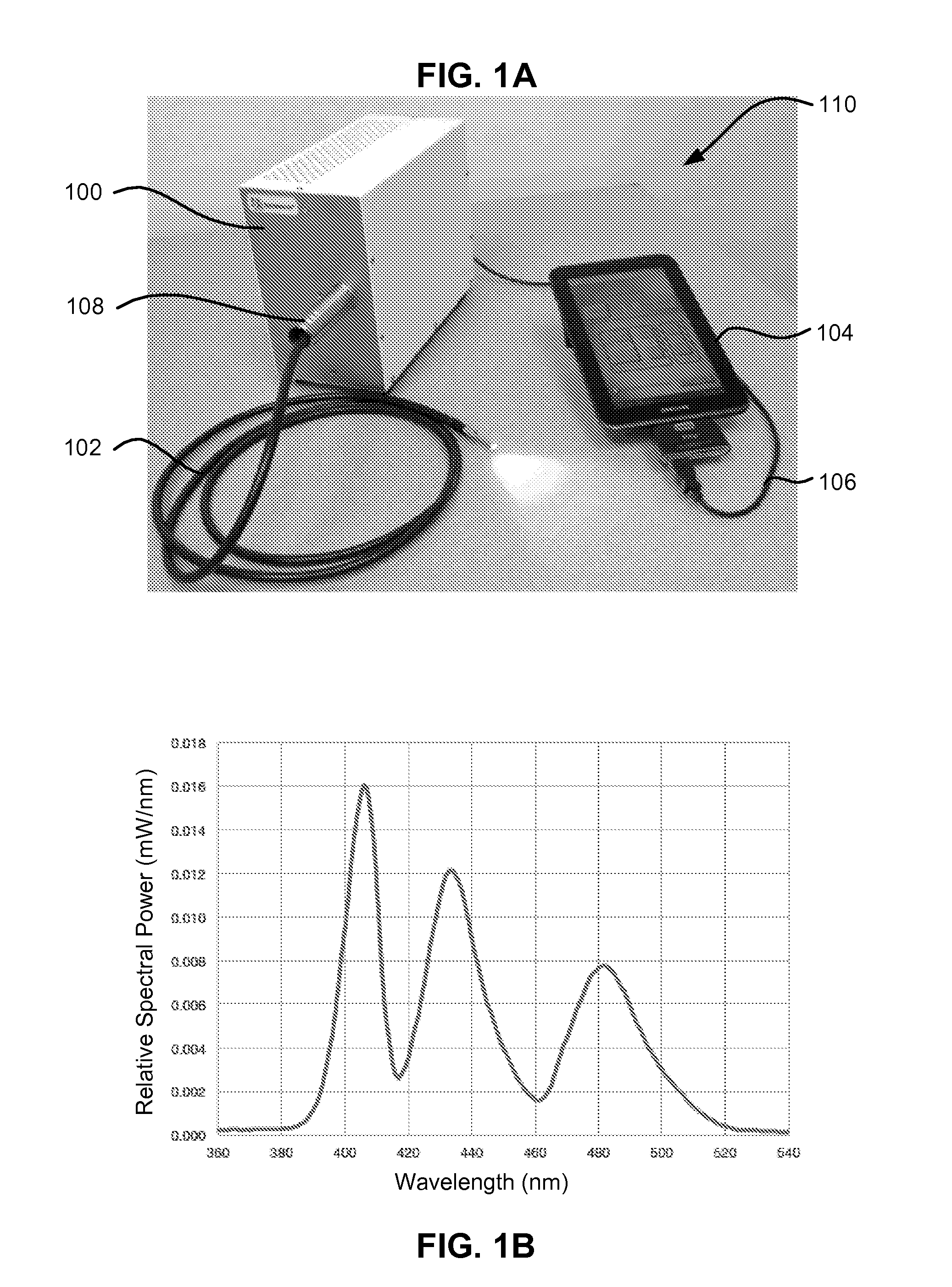
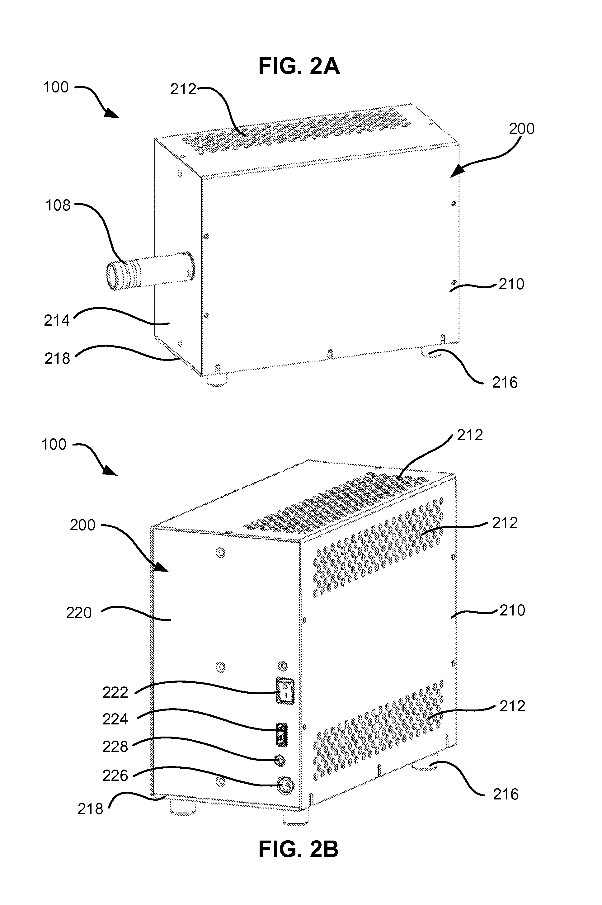
[0036]While no one lighting solution can best satisfy all instrument architectures, an LED light engine according to an embodiment of the invention combines the best of solid state technologies to meet or outperform the traditional technologies listed in Table I on the basis of all figures of merit across all wavelengths desired for photocuring. In an embodiment of the invention, an LED light engine can emit light exceeding 500 mW / color with intensifies up to 10 W / cm2 at wavelength suitable for photocuring. The present invention offers a smart alternative for light generation. The capabilities of the LED light engine are highlighted in Table II. The high performance illumination provided by the LED light engine is embodied in a single compact unit designed to replace the entire ensemble of lighting components. The sources, excitation filters, multicolor switching capabilities and fast pulsing are contained within one box with a small footprint ...


PUM


Abstract

A compact passively-cooled solid state illumination system is provided as a replacement for conventional arc light, metal halide and Xenon white-light sources for photocuring applications. The solid state illumination system utilizes LED modules to generate high intensity light output suitable for photocuring. The light output is continuous in the visible spectrum from 380 nm to 530 nm and is suitable for photocuring using a wide range of photoinitiators. A touchscreen interface allows programming of spectral output, intensity and duration. Output can be initiated using the touchscreen interface and / or a foot pedal.

Description

CLAIM OF PRIORITY[0001]The present application claims priority to U.S. Provisional Patent Application entitled “Solid State Light Source For Photocuring” Application No. 61 / 660,386, filed on Jun. 15, 2012 which application is incorporated herein by reference.RELATED APPLICATIONS[0002]The present application is related to the following patents and patent applications which are incorporated herein by reference in their entireties:[0003]U.S. Pat. No. 7,846,391, granted Dec. 7, 2010, entitled “Bioanalytical Instrumentation Using A Light Source Subsystem,” U.S. Publication No. 2007 / 0281322 filed May 21, 2007;[0004]U.S. Pat. No. 7,709,811, granted May 4, 2010 entitled “Light Emitting Diode Illumination System,” U.S. Publication No. 2009 / 0008573 filed Jul. 2, 2008;[0005]U.S. Pat. No. 8,098,375, granted Jan. 17, 2012 entitled “Light Emitting Diode Illumination System,” U.S. Publication No. 2009 / 0040523 filed Aug. 5, 2008;[0006]U.S. patent application Ser. No. 13 / 012,658, filed Jan. 24, 2011...

Claims


Application Information

Patent Timeline
Patent Type & Authority Applications(United States)
IPC IPC(8): F21V29/00F21V8/00G02B27/10F21V11/00
CPCF21V29/004F21V11/00G02B6/0008G02B27/10G02B27/141G02B6/3849G02B6/4292G02B2006/4297G02B6/4269G02B6/0006A61C19/003F21V29/83F26B3/28
Inventor JAFFE, CLAUDIA B.JAFFE, STEVEN M.TYLINSKI, GEORGE S.
Owner LUMENCOR
Why Eureka
Eureka Blog
Learn More