
Embedded power management control circuit

a power management control and embedded technology, applied in the direction of printed circuit parts, printed circuit non-printed electric components association, instruments, etc., can solve the problems of excessive volume and area of power control circuits on printed circuit boards, and achieve the effects of saving space, increasing heat dissipation, and saving additional real esta

Inactive Publication Date: 2005-09-22
INTERNATIONAL RECTIFIER COEP
View PDF4 Cites 126 Cited by
  • Summary
  • Abstract
  • Description
  • Claims
  • Application Information

AI Technical Summary

Benefits of technology

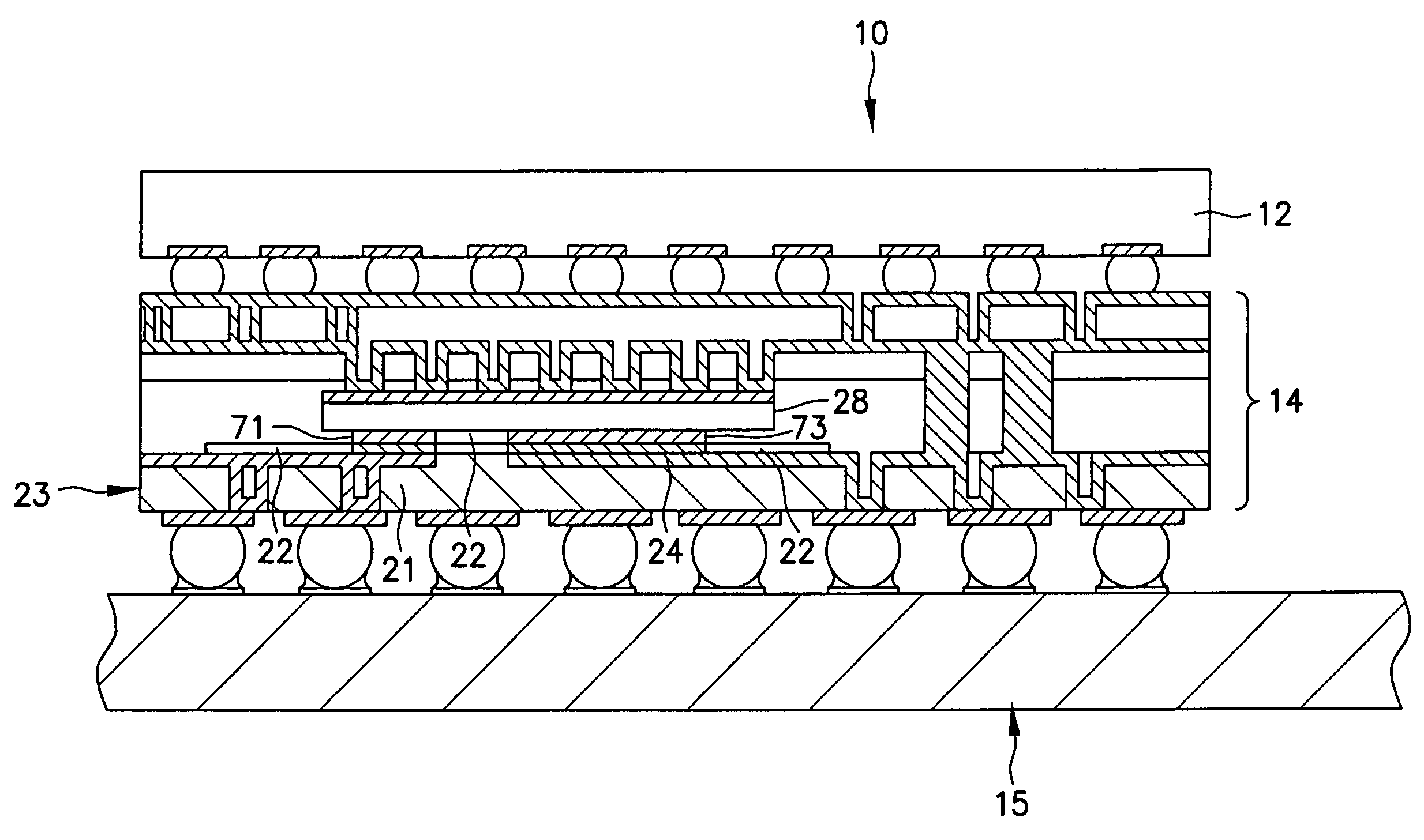
[0006] An embedded power management control circuit according to one embodiment of the present invention comprises a control board module assembled with an integrated circuit power converter in a vertical stack for attachment to a motherboard of a handheld device. The control board module, including a power transistor such as a field effect transistor (FET), and / or an integrated circuit mounted below the power supply integrated circuit, saving space on the motherboard of the device. Passive devices (e.g., resistors, capacitors and inductors) may also be embedded in the control board module saving additional real estate on the motherboard of the device. For example a circuit containing a MOSFET, IC and passive components may be embedded within a carrier having a land grid array pad arrangement that may be soldered to a mother board. A heatsink may be attached to the assembly in order to increase the heat dissipation to the ambient surrounding the embedded components.
[0007] One object of the present invention is to package a peripheral electronic system for a small portable electronic apparatus in a module which exhibits a small footprint and small volume.
[0008] A more particular object of the invention is to provide such a compact peripheral electronic system which can serve as a power converter and power control module for convenient attachment to a motherboard in a small electronic device such as a cell phone or the like.

Problems solved by technology

Conventional assembly of such power control circuits on printed circuit boards consume excessive volume and area.

Method used


Image

  • Embedded power management control circuit
  • Embedded power management control circuit
  • Embedded power management control circuit

Examples


Embodiment Construction

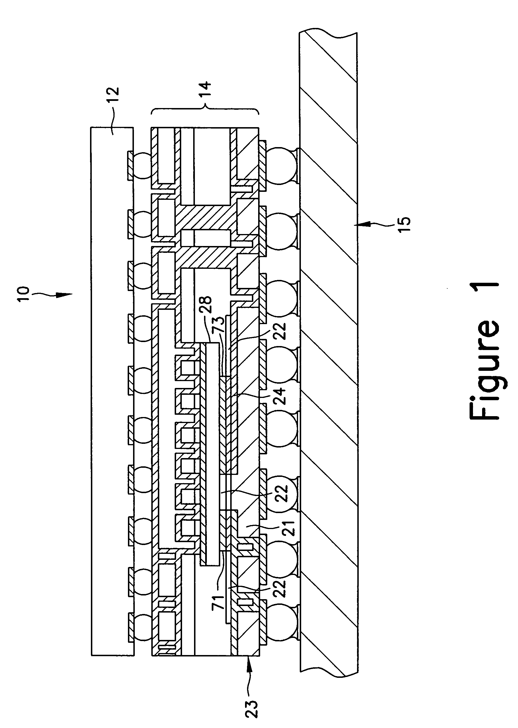
[0019] An embedded power management point of load delivery control circuit assembly 10 is illustrated in FIG. 1. A control board 14 is interposed between a power integrated circuit 12, such as a d-c to d-c power converter, and a motherboard 15 of an electronic device. For example, the electronic device may be a small cellular phone, which requires optimal use of the printed circuit board real estate in order to reduce the size of the device.

[0020] The power IC 12 may contain control circuitry for a synchronous buck converter, a control MOSFET, a synchronous MOSFET, over-current / over-voltage protection and over-temperature protection. Alternatively, power IC 12 maybe a power supply module of any other suitable or desired architecture and construction. Embedded passive devices, such as resistors, capacitors and inductors may be added in layers appended to the die surface. Power transistors such as field effect transistors (FETs) are embedded in control board 14 interposed between the...


PUM


Abstract

A peripheral electronic system for an electronic device including a motherboard having multiple individual electrically connected vertically stacked modules, at least one of which is a circuit board assembly including active and / or passive electronic components embedded therein with the components being electrically connected by conductive traces to provide desired operating function. The peripheral electronic system further includes an electrical connector array on an exposed surface of the composite structure to provide electrical connections between the peripheral electronic system and the motherboard.

Description

RELATED APPLICATION [0001] The present application is based on and claims the benefit of U.S. Provisional Application No. 60 / 552,143, filed on Mar. 11, 2004, entitled EMBEDDED POWER MANAGEMENT CONTROL CIRCUIT, the entire contents of which are expressly incorporated herein by reference.FIELD OF THE INVENTION [0002] The present invention relates broadly to compact assemblies of semiconductor electronic systems, and more particularly, to such systems in which compactness is achieved by embedding active and passive electronic devices in circuit boards of constituent subsystems which are then assembled in vertical stacks. One specific application of this invention is to power management control circuit modules which can be assembled with power converters for use in small, portable electronic devices. Alternatively, the embedded power management control circuit may be modified for use in circuits containing a power transistor device and controller. Such applications include audio class D ...

Claims


Application Information

Patent Timeline
IPC IPC(8): G06F1/16H05K1/14H05K1/18H05K3/34
CPCH05K1/141H05K2201/10734H05K3/3436H05K1/185H01L24/24H01L24/82H01L2224/04105H01L2224/12105H01L2224/16225H01L2224/2518H01L2924/13055H01L2924/13063H01L2924/13091H01L2924/14H01L2924/19105H01L2924/00
Inventor PAVIER, MARKSAMMON, TIM
Owner INTERNATIONAL RECTIFIER COEP
Learn More