Method of Coating a Component, Method of Forming Cooling Holes and a Water Soluble Aperture Plug

a technology of aperture plugs and components, applied in the direction of microcapsules, mechanical devices, machines/engines, etc., can solve the problems of at least partially blocking, affecting the application of tbc, and difficult to incorporate both systems

Active Publication Date: 2013-11-14
GENERAL ELECTRIC CO
View PDF14 Cites 14 Cited by
  • Summary
  • Abstract
  • Description
  • Claims
  • Application Information

AI Technical Summary

Benefits of technology

[0005]According to an exemplary embodiment of the present disclosure, a method of coating a component is provided. The method includes providing the component having a surface and including a plurality of apertures formed therein. The method includes masking at least one of the plurality of apertures with a plug, the plug comprising a removable material. The method includes applying at least one coating to the surface of the component. The method includes eliminating the removable material leaving open apertures in the surface of the coated component.

Problems solved by technology

Since high temperatures can damage the alloys used for the components, a variety of approaches have been used to raise the operating temperature of the metal components.
However, incorporation of both systems can be very difficult.
For example, the cooling holes sometimes cannot be formed in the engine part after a TBC has been applied, since lasers usually cannot effectively penetrate both the ceramic material and the metal to form the pattern of holes.
If the cooling holes are formed prior to the application of the TBC system, they may become covered and at least partially obstructed when the bond coat and / or TBC is applied.
Complete removal of the ceramic-metal material from the holes can be very time-consuming and ineffective, if not impossible.
Any obstruction of the holes during engine operation can interfere with the passage of cooling air, can waste compressor power, and can possibly lead to engine component damage due to overheating.

Method used


Image

  • Method of Coating a Component, Method of Forming Cooling Holes and a Water Soluble Aperture Plug
  • Method of Coating a Component, Method of Forming Cooling Holes and a Water Soluble Aperture Plug
  • Method of Coating a Component, Method of Forming Cooling Holes and a Water Soluble Aperture Plug

Examples


example 1

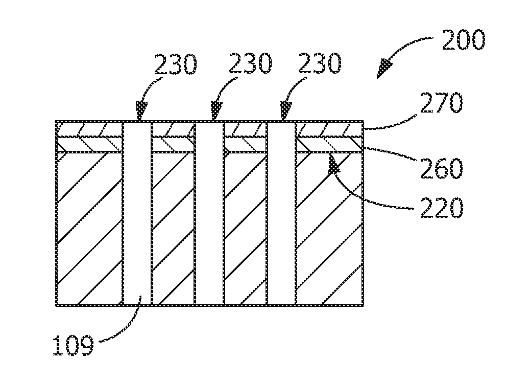
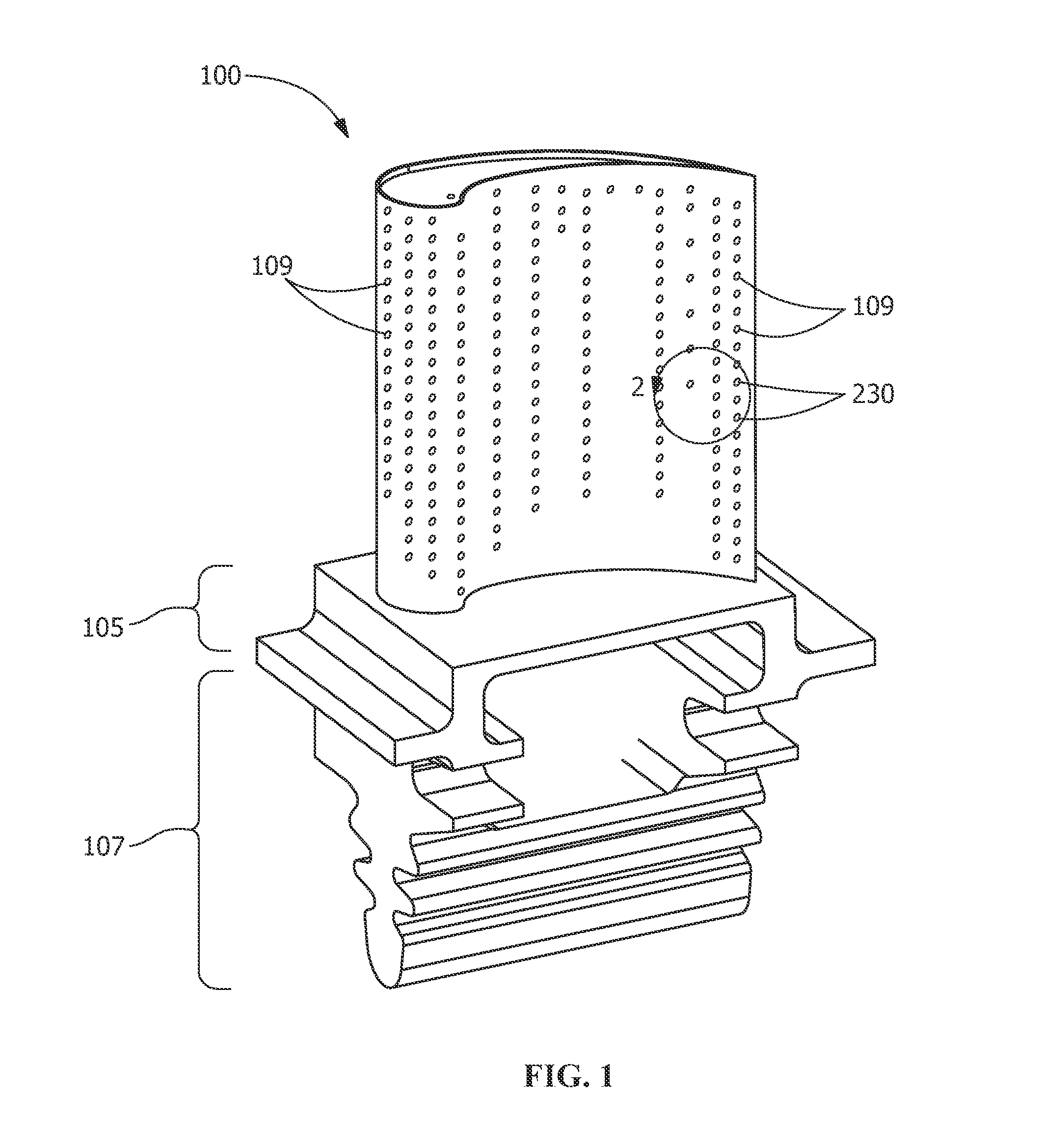
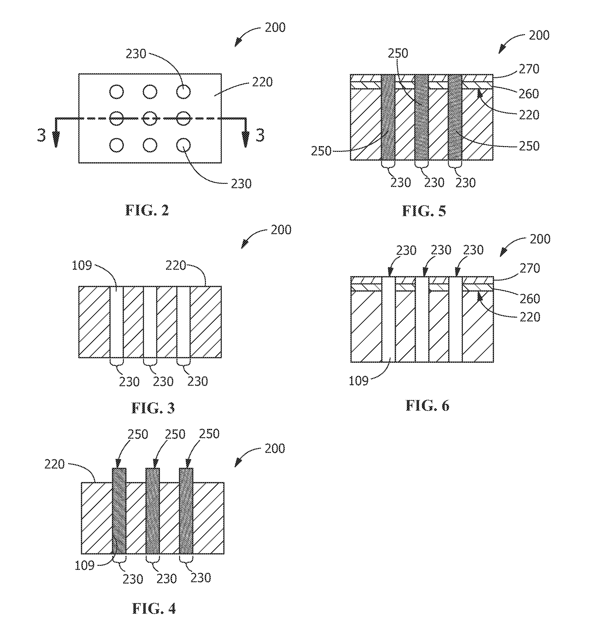
[0035]In one embodiment, plug 250 comprises, prior to drying, 60 g alumina flour, 25 g 30% colloidal silica binder, and 15 g water. This composition is formed into a desired plug shape and is applied manually onto aperture 230, a cooling hole opening on a surface of a gas turbine stage 1 nozzle. A High Velocity Oxygen Fuel (HVOF) Thermal Spray process is used to apply first coating 260, a bond coating, to surface 220 of component 200. Next, second coating 270, a TBC, is applied to first coating 260 using Air Plasma Spray (APS) process. Next, component 200 is dipped into a bath containing warm water to dissolve plug 250, leaving a component 200 having a bond coat, a TBC and open apertures 230. After removing plugs 250 from apertures 230, final heat treatment is applied to component 200 to cure the applied bond coating and TBC.

example 2

[0036]In another embodiment, plug 250 comprises a graphite paste. The graphite paste includes fine carbon powder dispersed in a solvent (aqueous or non-aqueous) and may include special additives for adjusting viscosity, preventing adhesion to cooling holes, and preventing corrosion. Graphite paste is applied manually into apertures 230, or cooling hole openings, on surface 220 of component 200, a gas turbine stage 1 nozzle. A HVOF Thermal Spray process is used to apply first coating 260, a bond coating to surface 220 of component 200. Next, second coating 270, a TBC, is applied to first coating 260 using an APS process. Component 200 including plug 250 is heated in an air furnace to about 538° C. (about 1000° F.) to oxidize / burn off plug 250 including graphite in apertures 230. After burn-off any remaining bits or pieces of plug 250 in apertures 230 is air blasted to remove the remnant powder. After removing plugs 250 from apertures 230, final heat treatment is applied to the compon...

example 3

[0037]In another embodiment, plug 250 comprises a mixture of acetone, polymethyl methacrylate (PMMA), and alumina. In making plug 250, 20 wt % PMMA is dissolved in acetone, then alumina is added to maximize the solids content to form a paste. The paste is applied to apertures 230, or in the cooling hole openings on a surface 220 of component 200, a gas turbine stage 1 nozzle. The paste is dried forming plugs 250 in apertures 230. A HVOF Thermal Spray process is used to apply first coating 260, a bond coating to surface 220 of component 200. Next, second coating 270, a TBC, is applied to first coating 260 using an APS process. After applying first coating 260 and second coating 270, component 200 is dipped into an acetone tank to dissolve PMMA in plug 250. Acetone dissolves plug 250 leaving open apertures 230. Alternatively, ultrasonication may be used in combination with the acetone bath to remove plug 250 from apertures 230. After removing plugs 250 from apertures 230, final heat t...


PUM

PropertyMeasurementUnit
temperaturesaaaaaaaaaa
Curie Temperatureaaaaaaaaaa

Abstract

A method for coating a component and forming at least one cooling hole in a component is provided. The method includes providing the component having a surface and including a plurality of apertures formed therein. The method includes masking at least one of the plurality of apertures with a plug comprising a removable material. The method includes applying at least one coating to the surface of the component. The method includes eliminating the plug including removable material leaving open apertures in the surface of the coated component. Also provided is a water-soluble aperture plug including water soluble high temperature resistant filler materials including aluminum oxide, zirconium oxide, magnesium oxide, silicon dioxide, zircon, graphite, tungsten carbide, silicon carbide, silicon nitride, boron nitride, aluminum nitrides and binding agents and dispersants including phosphates, silicates, sugar, salt, gum, resin, polyvinyl alcohol (PVA), polyethylene glycol, and combinations thereof.

Description

FIELD OF THE INVENTION[0001]The present invention relates generally to a method of coating a component, a method of forming cooling holes, and a water soluble aperture plug.BACKGROUND OF THE INVENTION[0002]When turbines are used on aircraft or for power generation, they are typically run at a temperature as high as possible, for maximum operating efficiency. Since high temperatures can damage the alloys used for the components, a variety of approaches have been used to raise the operating temperature of the metal components. One approach calls for the incorporation of internal cooling channels in the component, through which cool air is forced during engine operation. The cooling holes can be formed in the substrate by specialized laser-drilling techniques. Cooling air (usually provided by the engine's compressor) is fed through the holes from the cooler side to the hot side of the combustor wall. As long as the holes remain clear, the rushing air will assist in lowering the tempera...

Claims


Application Information

Patent Timeline
Patent Type & Authority Applications(United States)
IPC IPC(8): B05D1/32C08K5/07C08K3/04B05D1/34C08K3/08
CPCF01D5/288F01D5/286C23C4/01C23C4/02C23C4/073Y02T50/60
Inventor EMINOGLU, CEM MURATHARDWICKE, CANAN USLULEVY, LAWRENCE MATTHEW
Owner GENERAL ELECTRIC CO
Why Eureka
Try Eureka