
Vehicle wireless charger safety system

a wireless charger and safety system technology, applied in the direction of battery/fuel cell control arrangement, safety/protection circuit, anti-theft devices, etc., can solve the problems of increasing the cost of precious metals (, platinum, palladium, etc.) used in catalytic converters in vehicles, and the theft of precious metals

Active Publication Date: 2013-09-26
FORD GLOBAL TECH LLC
View PDF5 Cites 118 Cited by
  • Summary
  • Abstract
  • Description
  • Claims
  • Application Information

AI Technical Summary

Benefits of technology

The present invention is about a wireless charging system for devices, especially in vehicles. The system includes a charger region and a wireless charger which generates electric charging signals to charge the device. A proximity sensor is also included to sense the presence of objects near the charging region. When an object is detected, the wireless charger is controlled to reduce the charging signals to prevent damage or other negative effects from the object. This feature ensures safe and efficient wireless charging in various environments.

Problems solved by technology

Over the past decade, a rise in the cost of precious metals (e.g., platinum, palladium, rhodium and gold) has spurred an increase in thefts of catalytic converters used in vehicles.
The threat to vehicle dealerships is acute, as many dealerships possess hundreds of vehicles parked in showrooms and outdoor lots.
Trucks, vans and SUVs are particularly vulnerable to catalytic converter theft as these vehicles sit high off of the ground.
These components and devices are fairly expensive and may approach $300, up to a third of the replacement cost of the catalytic converter.
In addition, these mechanically-oriented catalytic converter theft deterrent and preventions systems can add appreciable weight to the vehicle with an adverse effect on fuel efficiency.
Even if the thief or other would-be criminal is deterred from tampering with and / or stealing the catalytic converters afforded protection by these mechanical devices, these individuals may still inflict significant damage to the vehicle before being deterred.

Method used


Image

  • Vehicle wireless charger safety system
  • Vehicle wireless charger safety system
  • Vehicle wireless charger safety system

Examples


Embodiment Construction

[0032]As required, detailed embodiments of the present invention are disclosed herein; however, it is to be understood that the disclosed embodiments are merely exemplary of the invention that may be embodied in various and alternative forms. The figures are not necessarily to a detailed design; some schematics may be exaggerated or minimized to show function overview. Therefore, specific structural and functional details disclosed herein are not to be interpreted as limiting, but merely as a representative basis for teaching one skilled in the art to variously employ the present invention.

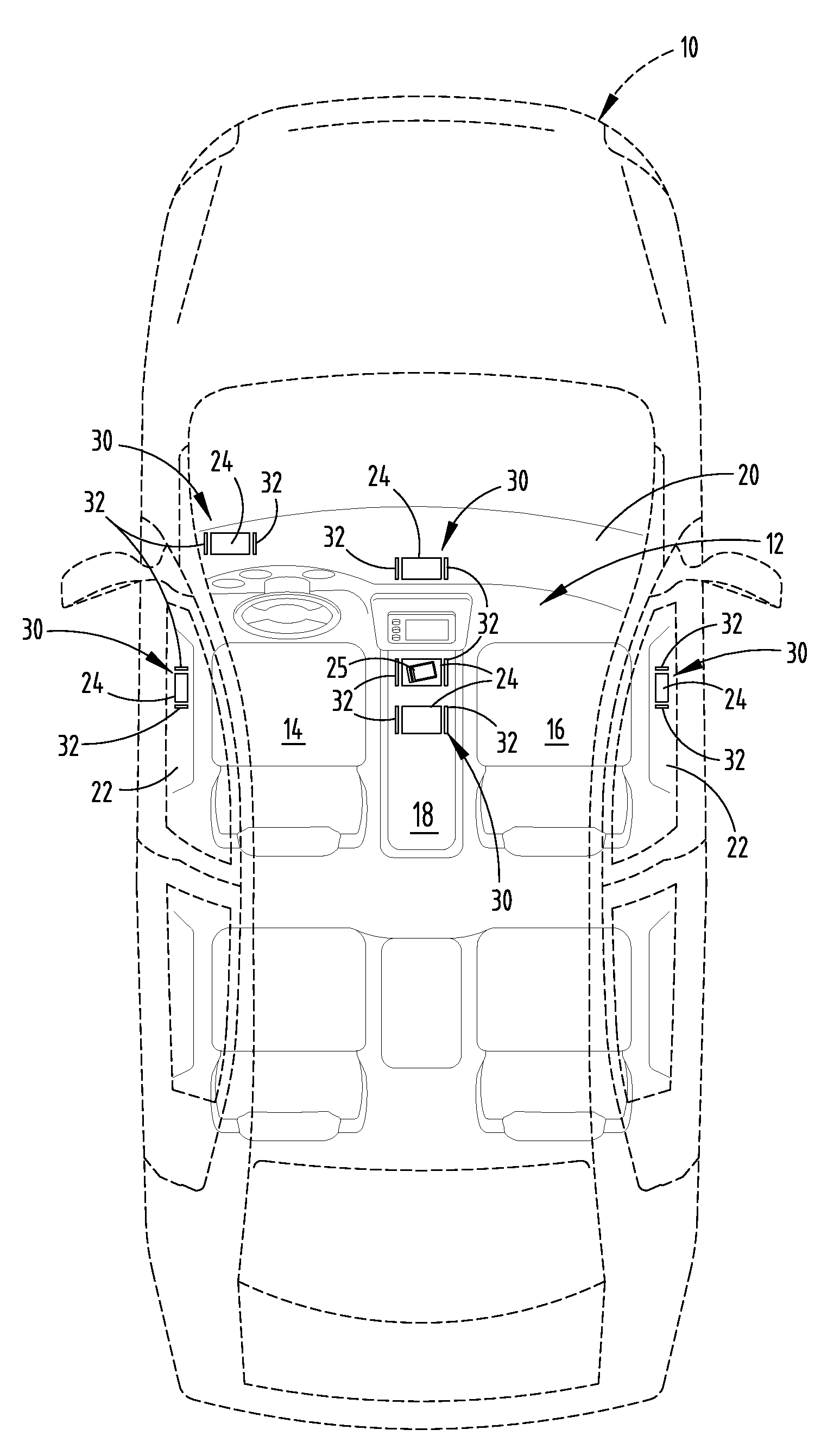
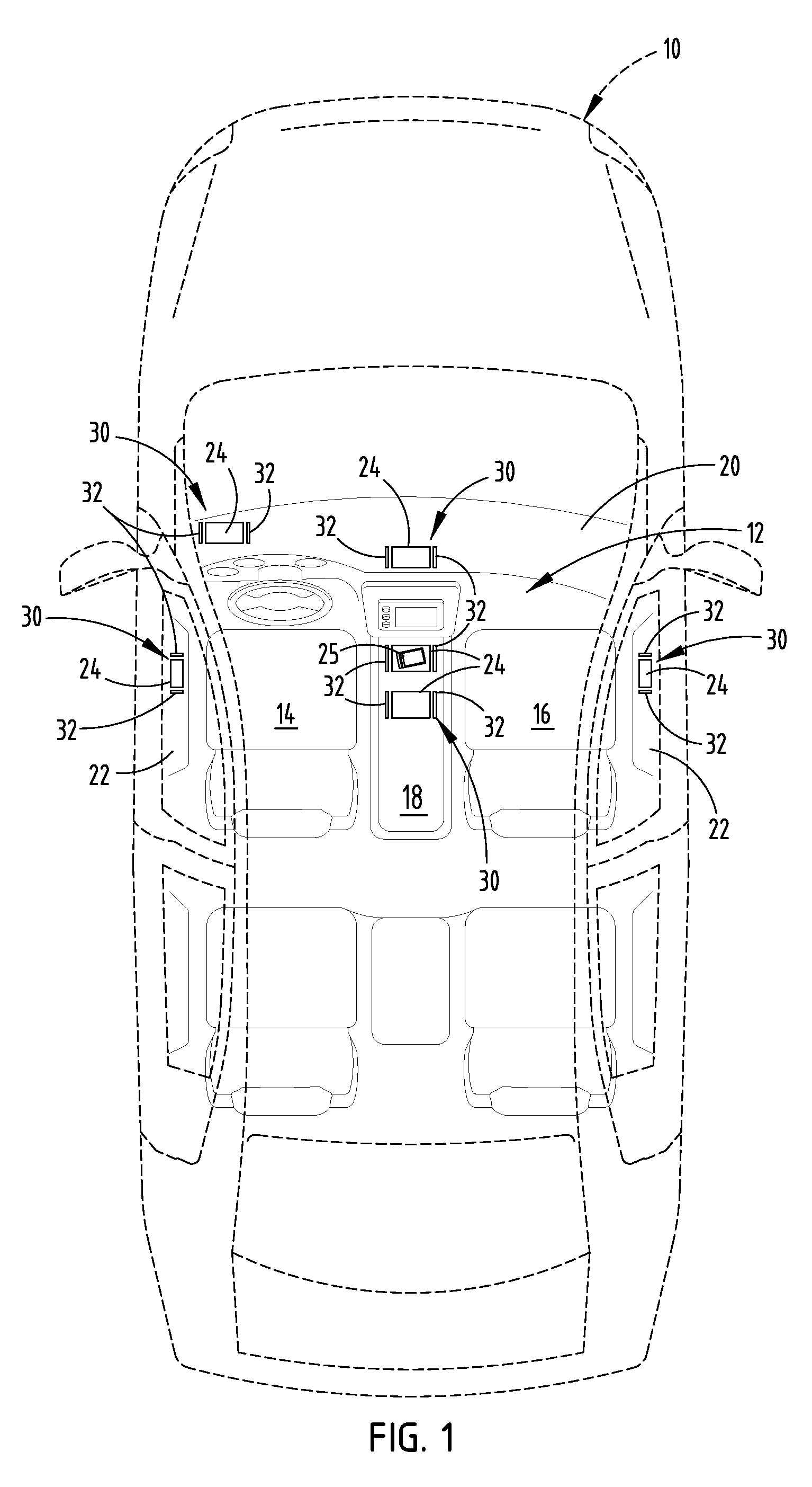
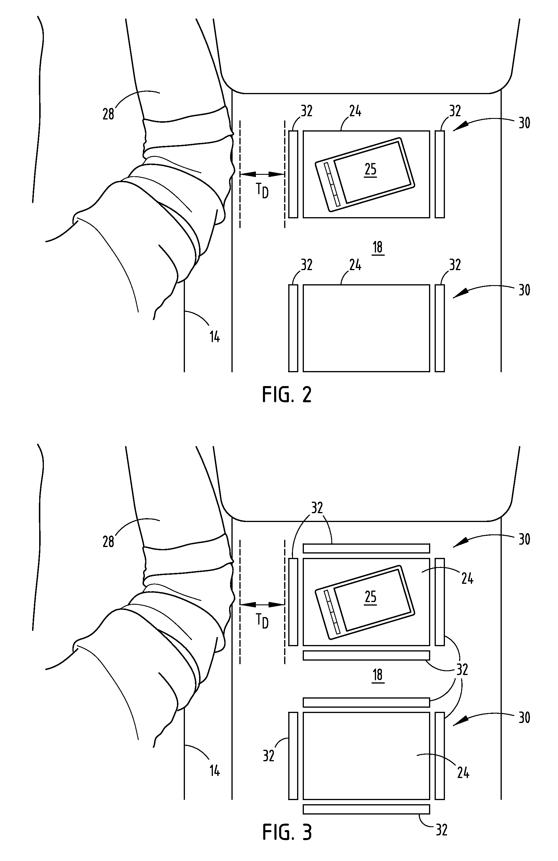
[0033]Referring to FIGS. 1-3, the interior of an automotive vehicle 10 is generally illustrated having a passenger compartment 12 employing various embodiments of a wireless charging system 30. The vehicle 10 generally includes a seating arrangement including a front driver seat 14 and front passenger seat 16, each adapted to seat a person as an occupant in passenger compartment 12 of the vehicle ...


PUM


Abstract

A vehicular charging system is provided that includes a battery and a charger region. The system also includes a wireless charger for generating an electric charging signal in the charger region to charge the battery, and a plurality of sensors located to sense foreign objects and living beings in proximity to the charger region. The system further includes a controller for controlling the charger to at least reduce the charging signal when a foreign object or a living being is in proximity to the charger region. The controller may be configured to terminate the charging signal and / or activate an alarm element when a foreign object or a living being is in proximity to the charger region.

Description

CROSS-REFERENCE TO RELATED APPLICATION[0001]This application is a continuation-in-part of U.S. patent application Ser. No. 13 / 282,933, filed on Oct. 27, 2011, entitled “WIRELESS CHARGING SYSTEM HAVING SENSE SHUTDOWN AND METHOD THEREFOR,” U.S. patent application Ser. No. 13 / 726,441, filed Dec. 24, 2012, entitled “RESISTANCE-BASED CATALYTIC CONVERTER PROTECTION SYSTEMS AND CONFIGURATIONS” and U.S. patent application Ser. No. 13 / 726,436, filed Dec. 24, 2012, entitled “CAPACITANCE-BASED CATALYTIC CONVERTER PROTECTION SYSTEMS AND CONFIGURATIONS.” The aforementioned related applications are hereby incorporated by reference in their entirety.FIELD OF THE INVENTION[0002]The present invention generally relates to wireless vehicle charging systems and, more particularly, relates to reducing exposure to foreign objects and living beings in proximity to such systems from the electric signal generated by the charging systems.BACKGROUND OF THE INVENTION[0003]Battery operated electronic devices, s...

Claims


Application Information

Patent Timeline
Patent Type & Authority Applications(United States)
IPC IPC(8): B60R25/10H02J7/02B60L50/16
CPCB60R25/1004H02J7/0029H02J7/025B60L7/14B60L2210/40B60L2240/662B60L2250/10B60L2270/145B60L2270/147Y02T90/16Y02T10/7072Y02T10/70Y02T90/14B60L53/14B60L50/16B60L53/36B60L53/37B60L58/21B60L50/66B60L53/124Y02T10/72Y02T90/12H02J50/60H02J50/10B60L53/12
Inventor VAN WIEMEERSCH, JOHN ROBERTKAUTZ, RICHARD WILLIAMSALTER, STUART C.GARDNER, CORNEL LEWISPRICE, DON DAVID
Owner FORD GLOBAL TECH LLC
Learn More