
Inductive coupling circuit and telecommunication method by sheathed cables of an electrical current distribution network

a technology of inductive coupling circuit and telecommunication method, which is applied in the direction of ignition automatic control, electric controllers, instruments, etc., can solve the problems of reducing the voltage at the impedance of the line and the consumer, and unable to provide a global alternative to existing telecommunication networks. , to achieve the effect of low loss

Active Publication Date: 2010-03-09
IAD GESELLSCHAFT FUER INFORMATIK AUTOMATISIERUNG & DATENVERARBEITUNG MBH
View PDF11 Cites 0 Cited by
  • Summary
  • Abstract
  • Description
  • Claims
  • Application Information

AI Technical Summary

Benefits of technology

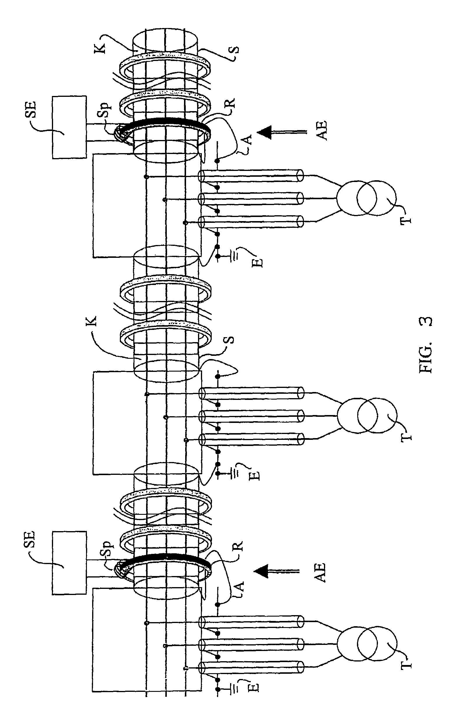
[0032]The inductive coupling circuits according to the invention have the advantage that by coupling the current into the conductor, the transmission of data is no longer limited to the transmission route between neighboring transformer stations. Since, in most cases, a transformer represents a load of relatively high impedance, most of the current remains in the line that is carried on. Thus, a high number of transformer stations can be bypassed without installing a transceiver unit (for repeater purposes) in these stations.
[0034]For decoupling, the current in the conductor which contains the message signal has to be separated from the current in the shield, which contains, due to the shielding effect, a return current and interference signals. The purpose of a shield in a cable is to reduce the electromagnetic field outside the cable. For this purpose, the shield, which is connected at both ends with low impedance, contains a current in the opposite direction so that the resulting magnetic fields outside the cable compensate each other. Inversely, an electromagnetic field of an interference source only induces a current into the shield, whereby in the cable the field caused by the interferer is compensated to a large extent. Thus, the conductor in the cable is not influenced by the interference and is excellently suitable for transmission of data.
[0036]As already described, no current flow in the shield is evaluated if there is no other conductive connection from one side of the plane defined for the inductive coupling to the other side than the connection through the plane itself. This type of decoupling now allows to exclusively evaluate the current in the conductor of the cable. Since the shield protects the conductor in the cable from induction of interferences, the remaining interference is low. Thus, the resulting ratio of wanted signal and interference signal is very favorable for data transmission. It enables a coverage which is partly superior to that reached by capacitive coupling modules. Assuming a distance between two transformer stations of approximately 450 m, a signal-to-noise ratio of approximately 60 dB can still be attained so that, overall, a transmission over distances of several kilometers and bypassing several transformer stations is still possible.
[0038]This further development of the invention is advantageous in that a protective housing is not required for the inductive coupling unit and that it can be installed without an air gap. However, every geometrical shape can, in principle, be chosen which is closed and thus defines a plane (e.g. a square) and it is also possible to use an air coil.
[0040]Embodiments of the invention are advantageous which allow even a mixed installation over one and all three phases with only low losses.

Problems solved by technology

After abolishment of the monopoly on telecommunication, wide range, intensive competition has started, which has not yet had major effect in the local network area.
However, due to their high expense they cannot provide a global alternative to existing telecommunication networks in the foreseeable future.
The superposition of the 50 Hz power current with high-frequency data signal currents generally involves problems of electromagnetic compatibility (EMC).
This spatial separation of outgoing conductor and return conductor causes the generation of high magnetic fields that influence adjacent electric circuits by induction and thus induce interference voltages.
This common mode current causes a decrease in voltage at the impedances of the line and the consumer, and thus represents another interference source.
The disadvantage of this coupling is the direct connection to the conductor, the respective required withstanding voltage, the space required for installation and the necessity of switching the system off for installation.
In very compact transformer stations that are supplied from underground cables, mostly new ones, the installation of a capacitive coupling unit is not always possible.
If a transmitter / receiver is defective, the transmission line is interrupted.
For some applications, which are critical with regard to real time capability or security requirements, this is not acceptable.
Hence, a capacitive coupling module as well as the installation of an inductive coupling module directly over a conductor are not possible.

Method used


Image

  • Inductive coupling circuit and telecommunication method by sheathed cables of an electrical current distribution network
  • Inductive coupling circuit and telecommunication method by sheathed cables of an electrical current distribution network
  • Inductive coupling circuit and telecommunication method by sheathed cables of an electrical current distribution network

Examples


Embodiment Construction

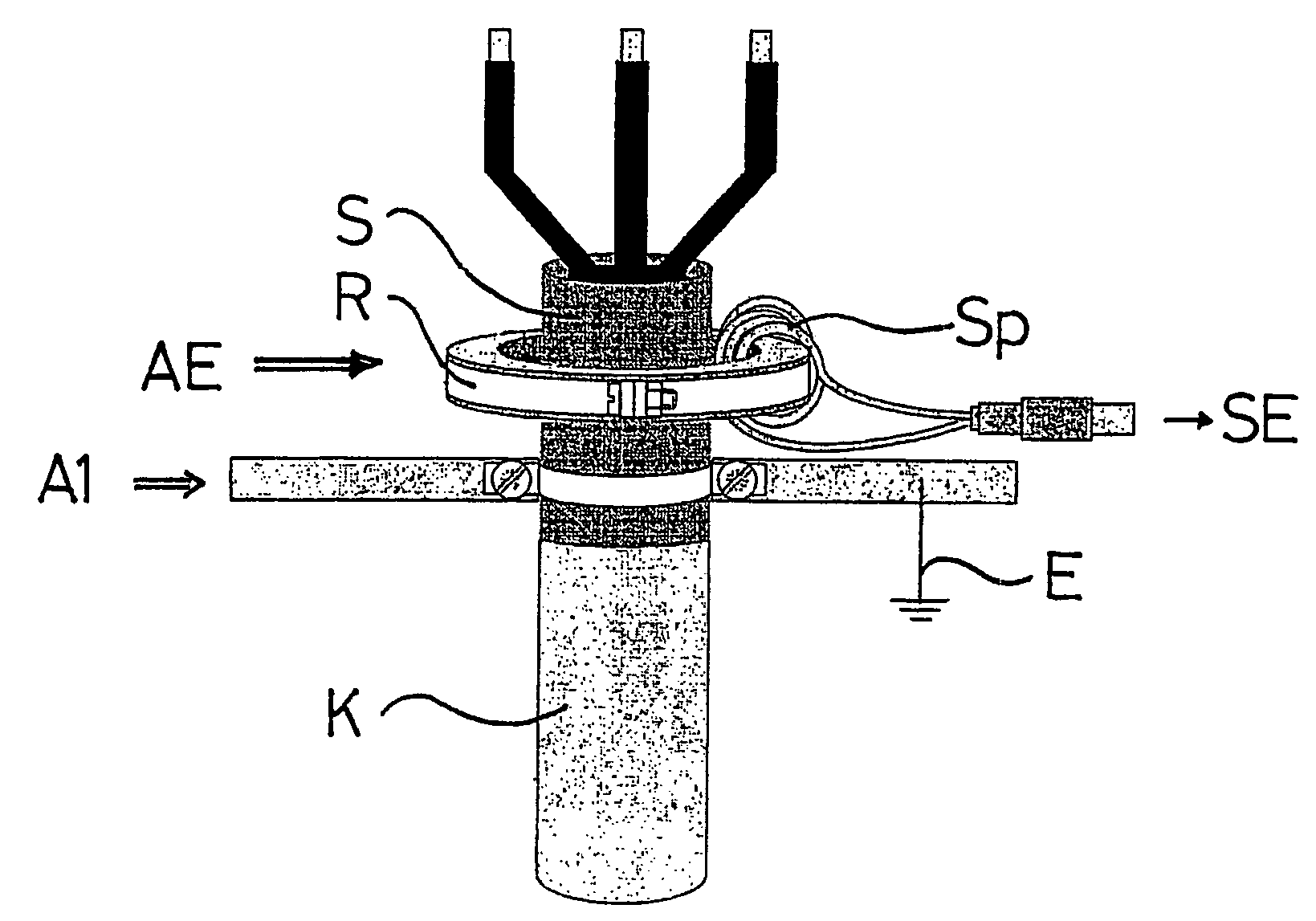
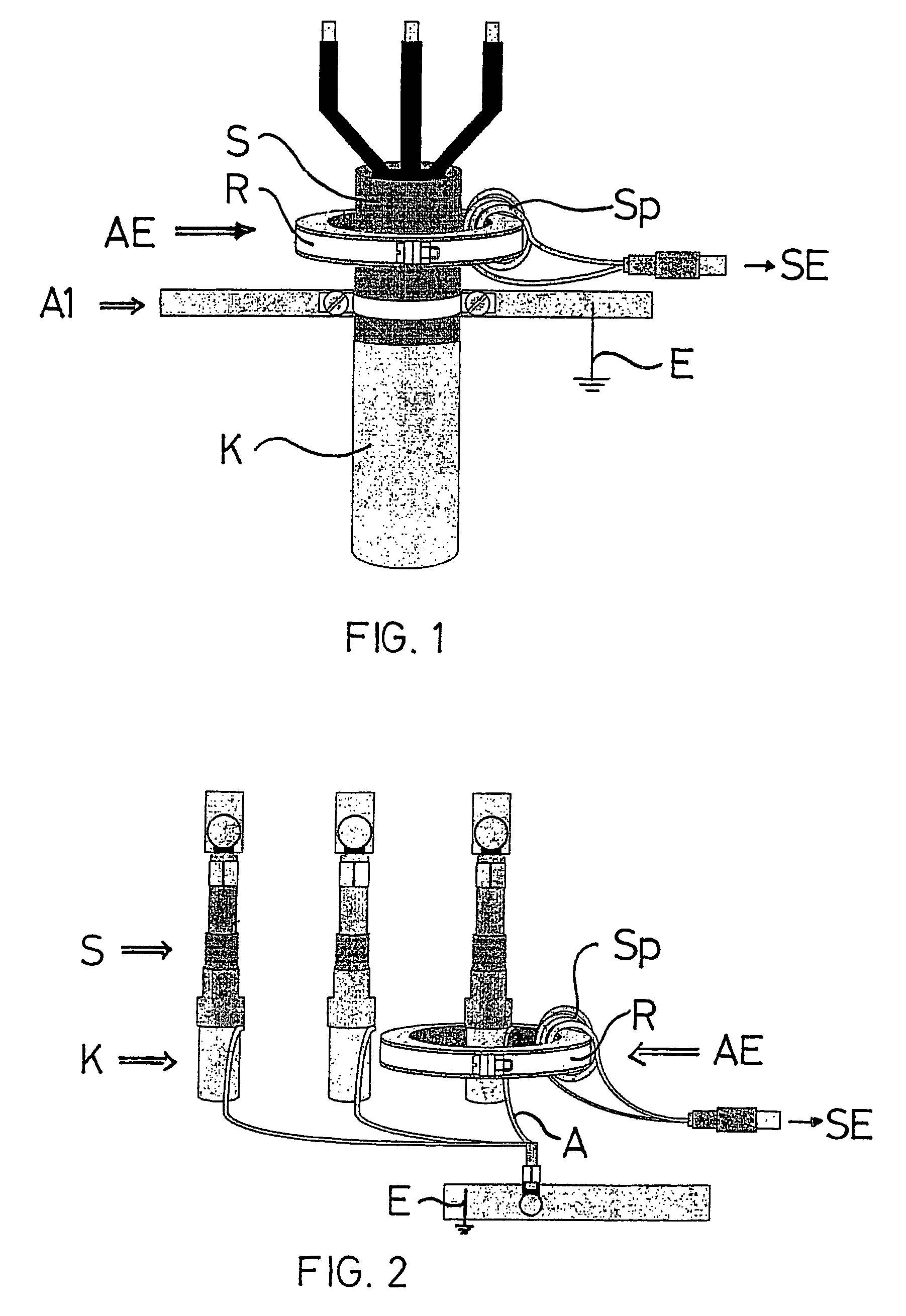
[0047]The embodiments of the inductive coupling circuit according to the invention shown in FIG. 1 and FIG. 2 are preferably used for information transmission in electric energy distribution networks, particularly in medium-voltage or high-voltage systems. Furthermore, it can be used for almost every cable type and application, for example even for pipelines (here the metal pipe quasi works as the shield and the medium as the conductor) or for energy cables for direct current transmission. Preferably, the inductive coupling circuit consists of an inductive coupling device / unit AE and an arrester / earth wire A1 (see FIG. 1) respectively A (see FIG. 2 and FIG. 3). The inductive coupling unit AE consists of a ring R enclosing the shielded power / energy cable K and a coil SP inductively coupled to the ring which is connected to a transceiver unit SE.

[0048]For the embodiment of the inductive coupling circuit according to the invention shown in FIG. 1, the earth wire A1 is subsequently conn...


PUM


Abstract

The various designs of capacitive or inductive coupling / decoupling fitted on cables in a medium voltage network are known, the inductive coupling circuits constantly inducing current in the sheath of the electric cable. The invention aims at obtaining ranges of capacitive coupling / decoupling for an inductive coupling circuit. Therefore, an inductive coupling unit comprising a ring enclosing the sheathed electric cable and a coil, coupled to said ring by induction and connected to a transmission and reception device, is designed such that, upon transmission the current of the message signal is directly induced in the conductor and, upon receptions only the conductor current is evaluated. In a first embodiment, a by-pass, located downstream of the inductive coupling unit and upstream of the defined surface, is connected to the sheath and to ground or to the compensation potential. In a second embodiment, a by-pass connected to the sheath and to the ground or to the compensating potential has a conduction path passing back through the ring core. The invention concerns telecommunication systems in current distribution electrical networks.

Description

[0001]This application is the national stage of PCT / EP2004 / 007646 filed on Jul. 11, 2004 and claims Paris Convention priority of DE 103 31 744.9 filed Jul. 11, 2003BACKGROUND OF THE INVENTION[0002]The invention primarily concerns an inductive coupling circuit. Furthermore, the invention relates to a telecommunication method in sheathed cables of an electric current distribution network.[0003]The creation of new fast access possibilities to the POTS (plain old telephone system) for telecommunication in the local network area—also called local loop or last mile—is currently the subject of intensive development. After abolishment of the monopoly on telecommunication, wide range, intensive competition has started, which has not yet had major effect in the local network area. The main reason for this is that the former monopolists are still the owners of the distribution networks. Alternatives in form of microwave wireless networks or cable TV networks are currently under development. Ho...

Claims


Application Information

Patent Timeline
IPC IPC(8): G05B11/01H04B3/56
CPCH04B3/56H04B2203/5487
Inventor BUMILLER, GERD
Owner IAD GESELLSCHAFT FUER INFORMATIK AUTOMATISIERUNG & DATENVERARBEITUNG MBH
Learn More