Ceramic cutting knife and method for manufacturing same

Inactive Publication Date: 2013-09-26
KYOCERA CORP
View PDF13 Cites 4 Cited by
  • Summary
  • Abstract
  • Description
  • Claims
  • Application Information

AI Technical Summary

Benefits of technology

The present invention provides a cutting knife with improved adhesion between the zirconia ceramic base member and the DLC layer, which helps maintain good hardness and sliding properties even in long-term use. Additionally, the invention utilizes the internal stress of the DLC layer on the surface of the nitride layer to create a zirconia ceramic cutting knife with high bending strength. These technical effects reduce the likelihood of nicked edges, maintain ease of cutting food, and improve the overall performance of the cutting knife.

Problems solved by technology

However, when ceramics are directly coated with the DLC film, the DLC film tends to peel from ceramics due to low adhesion of the DLC films because ceramics are not conductors.

Method used


Image

  • Ceramic cutting knife and method for manufacturing same
  • Ceramic cutting knife and method for manufacturing same
  • Ceramic cutting knife and method for manufacturing same

Examples


example

(Preparation of Sample)

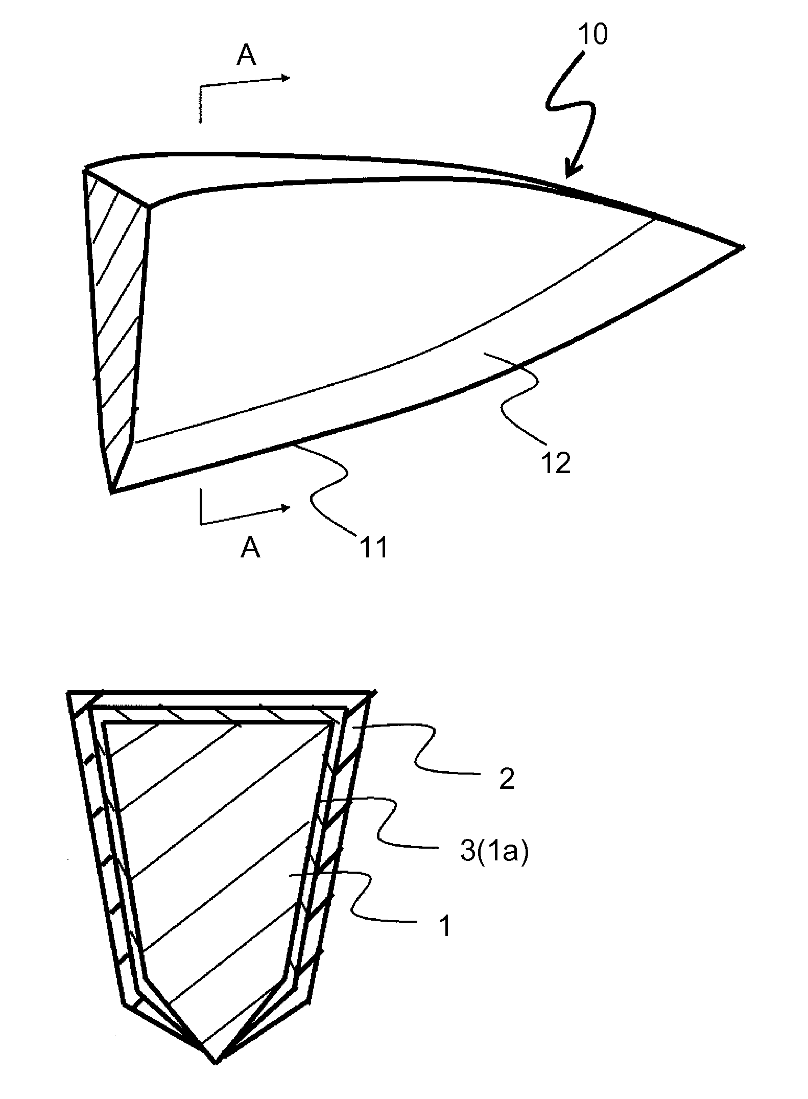
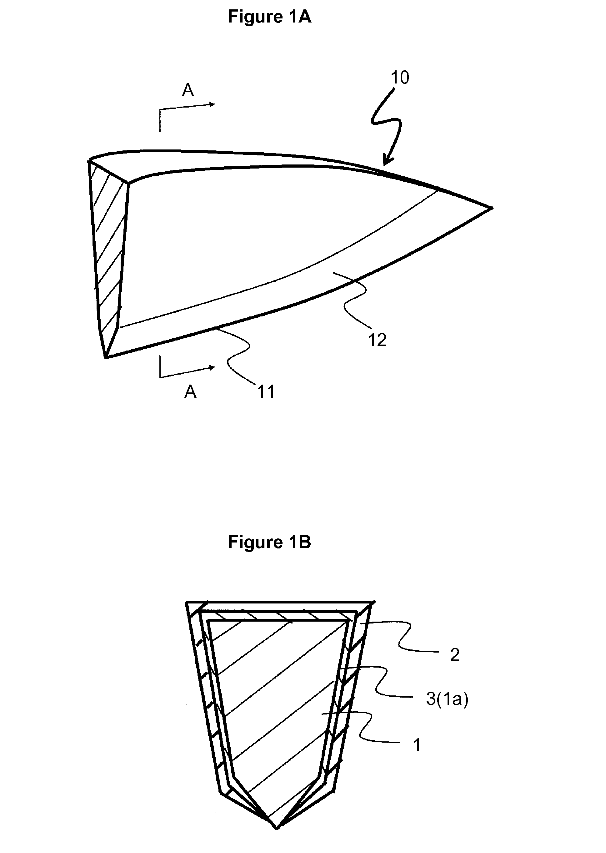
[0095]In an example, a zirconia ceramic cutting knife containing 2 mol % of yttria, 0.2% by mass of silica, 0.005% by mass of sodium oxide, 1% by mass of alumina, and the balance of zirconia was prepared as a base member 1.

[0096]This was produced by compression molding at a molding pressure of 100 MPa, and firing was performed at 1450° C. for 2 hours (Sample Nos. 3 to −22).

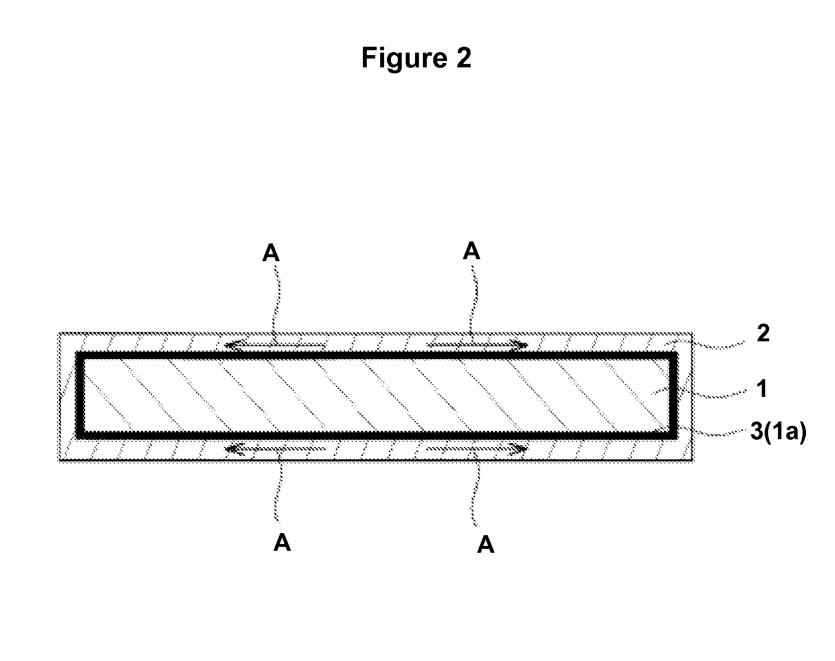
[0097]In the example, the nitride layers 3 (1a) were divided into ones formed by a sputtering method (Sample Nos. 3 to 5) and ones formed by an ion implantation method (Sample Nos. 6 to 22) with thicknesses shown in Table 1.

[0098]The DLC layers 2 were formed by a reactive CVD method to the thickness shown in Table 2 (Sample Nos. 3 to 22).

[0099]Sample Nos. 6 and 9 were formed under the same conditions and Sample Nos. 16 and 21 were formed under the same conditions as a matter of convenience.

[0100]In comparative examples (Sample Nos. 1, 2, and 23 to 25), it is divided such that the base member...


PUM


Abstract

A ceramic knife and a method for producing the ceramic knife are disclosed. The ceramic knife includes a base member and two layers on the base member. The base member includes zirconia as a main component. The base member further includes a cutting edge and a cutting edge portion that is adjacent area of the cutting edge. Two layers include a first layer and a second layer. The first layer is located at least on the cutting edge portion of the base member, and includes nitride material such as zirconium nitride, silicon nitride and aluminum nitride. The second layer is located on the first layer, and includes diamond-like carbon or DLS.

Description

TECHNICAL FIELD[0001]The present invention relates to a ceramic cutting knife and a method for producing the same.BACKGROUND ART[0002]In recent years, ceramics, particularly zirconia ceramics having good sliding properties and toughness, have been utilized as materials for knife such as a kitchen knife and the like. These ceramic cutting knifes may have surfaces coated with a diamond-like carbon (also referred to as “DLC” hereinafter) film for the purpose of enhancing hardness and sliding properties.[0003]However, when ceramics are directly coated with the DLC film, the DLC film tends to peel from ceramics due to low adhesion of the DLC films because ceramics are not conductors. Therefore, it is known that an underlying layer of a metal such as Ti, Cr, or the like is provided on a surface of ceramic, and a DLC film is formed on the underlying layer (refer to, for example, Patent Literature 1).CITATION LISTPatent Literature[0004]PTL 1: Japanese Unexamined Patent Application Publicati...

Claims


Application Information

Patent Timeline
IPC IPC(8): B26B9/00
CPCB26B9/00
Inventor KAWASUMI, YOSHIYUKINISHIHARA, TAKANORI
Owner KYOCERA CORP
Why Eureka
Try Eureka