
Method of and system for grinding pyrolysis of particulate carbonaceous feedstock

a technology of carbonaceous feedstock and pyrolysis method, which is applied in the direction of combustible gas production, lighting and heating apparatus, combustion types, etc., can solve the problems of large volume of inert gas, high cost of fine feedstock particles preparation, and substantive technical and economic constraints of commercial scal

Active Publication Date: 2013-08-08
RENERGI PTY LTD
View PDF11 Cites 17 Cited by
  • Summary
  • Abstract
  • Description
  • Claims
  • Application Information

AI Technical Summary

Benefits of technology

The present invention provides advantages over current pyrolysis techniques by allowing for the use of crude, irregularly shaped feedstock particles that may contain non-biomass particles. This means that no significant preliminary processing is needed. Additionally, the char produced is in the form of fine particles that are easy to use. No carrier gas is required, simplifying the process and reducing the generation of aerosols. There may also be more efficient use of non-condensable pyrolysis gas.

Problems solved by technology

However, these technologies may have substantive technical and economical constraints at the commercial scale.
For example, fluidized bed pyrolysers require the use of very fine particles, typically below 2 mm in diameter, but the preparation of such fine feedstock particles usually incurs high costs.
Another serious deficiency of fluidized beds is that a very large volume of inert gas is required in order to fluidize the inert solids and to carry the resulted char out of the reactor.
Many problems are associated with the use of a large volume of inert gas.
For example, the partial pressure of the organic vapour may become extremely low due to dilution by the inert gas, which makes it difficult to quench and collect the organic components.
In addition, a high velocity gas flow leads to the formation of aerosols which are extremely difficult to collect.
Furthermore, non-condensable pyrolysis gas generated in this process is also diluted by the large volume of inert gas, which makes the direct utilization of this gas more problematic (e.g. in a combustion facility for generating heat).
The continuous heating up (before entering the fluidized bed) and subsequent cooling down (to condense the organic vapour as bio-oil) of the inert gas greatly reduces the overall process efficiency.

Method used


Image

  • Method of and system for grinding pyrolysis of particulate carbonaceous feedstock
  • Method of and system for grinding pyrolysis of particulate carbonaceous feedstock
  • Method of and system for grinding pyrolysis of particulate carbonaceous feedstock

Examples


Embodiment Construction

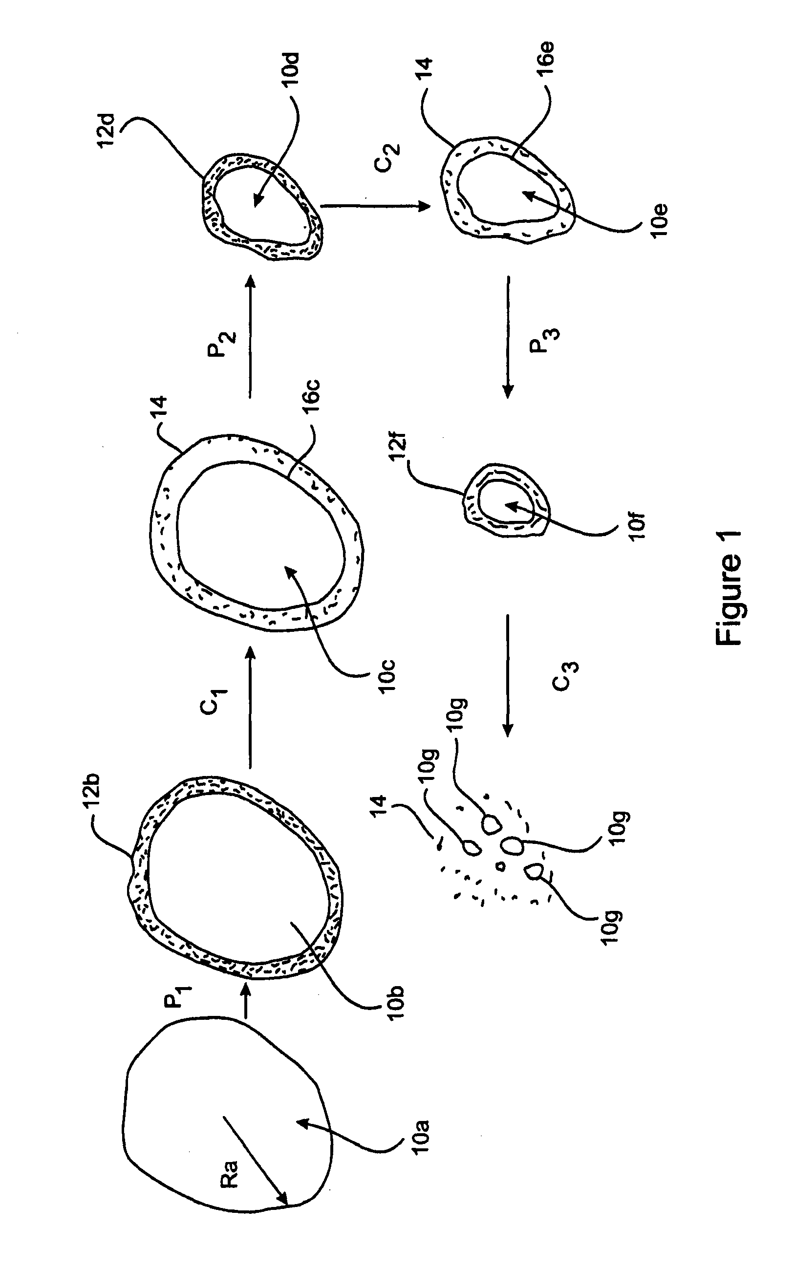
[0054]In its broadest form, embodiments of the present method and system of grinding and pyrolysis of particulate carbonaceous feedstock comprise subjecting particulate carbonaceous feedstock to simultaneous particle size reduction and pyrolysis. The present embodiments are described in the context of particulate biomass feedstock, however embodiments may be applied to or operable in relation to other forms or types of carbonaceous feedstock. Pyrolysis has the effect of forming a layer of char on a biomass particle and producing organic vapours. A particle size reduction process breaks the char layer from a biomass particle thereby reducing the size of that particle and exposing a relatively fresh outer layer of the particle. Pyrolysis of the reduced size biomass particle again results in the formation of a char layer on the newly exposed outer surface and further production of organic vapour. This char layer is broken off by the particle size reduction process. Thus the pyrolysis a...


PUM


Abstract

A pyrolysis plant 20 comprises a grinding pyrolyser 22, being a machine or apparatus in which both particle size reduction and pyrolysis occur simultaneously. Plant 20 also comprises a bin (hopper) 30 for holding wet particulate biomass feedstock. Chute 32 leads from the bin 30 to a biomass dryer 34 which reduces moisture content of the feedstock as low as possible, e.g., to below about 10. Dried feedstock is conveyed from dryer 34 via line 36 to a dried biomass feedstock hopper 38. Dried feedstock is fed from hopper 38 into a chute 40 which leads to an inlet trunnion 42 of grinding pyrolyser 22. A discharge trunnion 44 of grinding pyrolyser 22 leads to a char holder 60 for collecting char particles and a condensation train 62 for condensing vapour generated by the pyrolysis to produce oil.

Description

FIELD OF THE INVENTION[0001]The present invention relates to a method of and system for grinding pyrolysis of particulate carbonaceous feedstock such as, but not limited to, biomass or coal, particularly although not exclusively, for the production of one or more or a combination of: organic vapour, organic liquid (frequently in the form of oil) and char.BACKGROUND OF THE INVENTION[0002]Pyrolysis refers to the thermal decomposition of substances (feedstock) by heating in an oxygen deficient environment. Pyrolysis processes are generally divided into slow and fast pyrolysis according to the rate at which the feedstock is heated up. The traditional method of charcoal production is considered to be a slow pyrolysis process; it gives a liquid yield of typically around 30% (on dry mass basis). The fast pyrolysis of feedstock, on the other hand, gives a much higher liquid yield, widely reported to be above 60% (on dry mass basis). Therefore, the fast pyrolysis is advantageous over the slo...

Claims


Application Information

Patent Timeline
IPC IPC(8): C10B37/00
CPCC10B47/30C10B49/16C10B53/02C10B57/10C10J3/66C10J2300/0926C10B37/00F23G5/033F23G5/20F23G2201/303F23G2206/10Y02E50/14Y02E50/15F23G5/027Y02P20/129Y02P20/133C10G1/02Y02E20/12Y02E50/10C10B1/10Y02P20/145
Inventor LI, CHUN-ZHUWANG, XIAOSHANWU, HONGWEI
Owner RENERGI PTY LTD
Learn More