Eureka AIR delivers breakthrough ideas for toughest innovation challenges, trusted by R&D personnel around the world.

System and method for treating an amorphous alloy ribbon

a technology of amorphous alloys and ribbons, applied in the field of amorphous materials, can solve the problems of reducing the attractiveness of alloys, amorphous alloys producing about one third of the core loss of silicon steels, and the production of amorphous alloys is limited to a very thin ribbon of various widths, so as to increase or reduce tensile stress

Active Publication Date: 2013-06-06
HYDRO QUEBEC CORP
View PDF4 Cites 25 Cited by
  • Summary
  • Abstract
  • Description
  • Claims
  • Application Information

AI Technical Summary

Benefits of technology

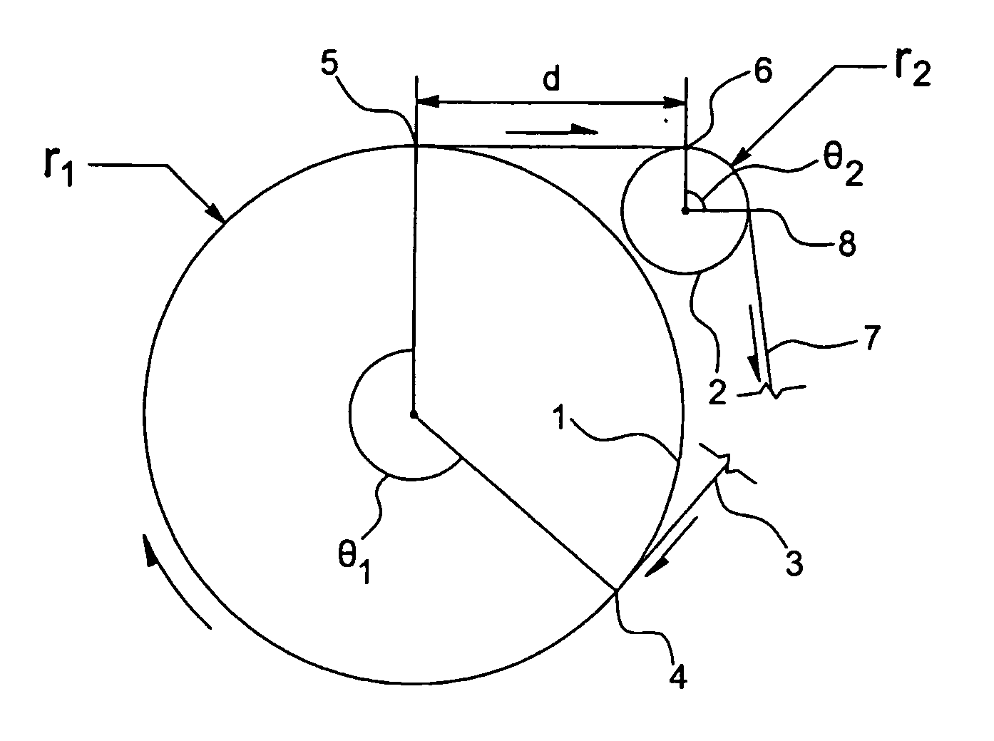
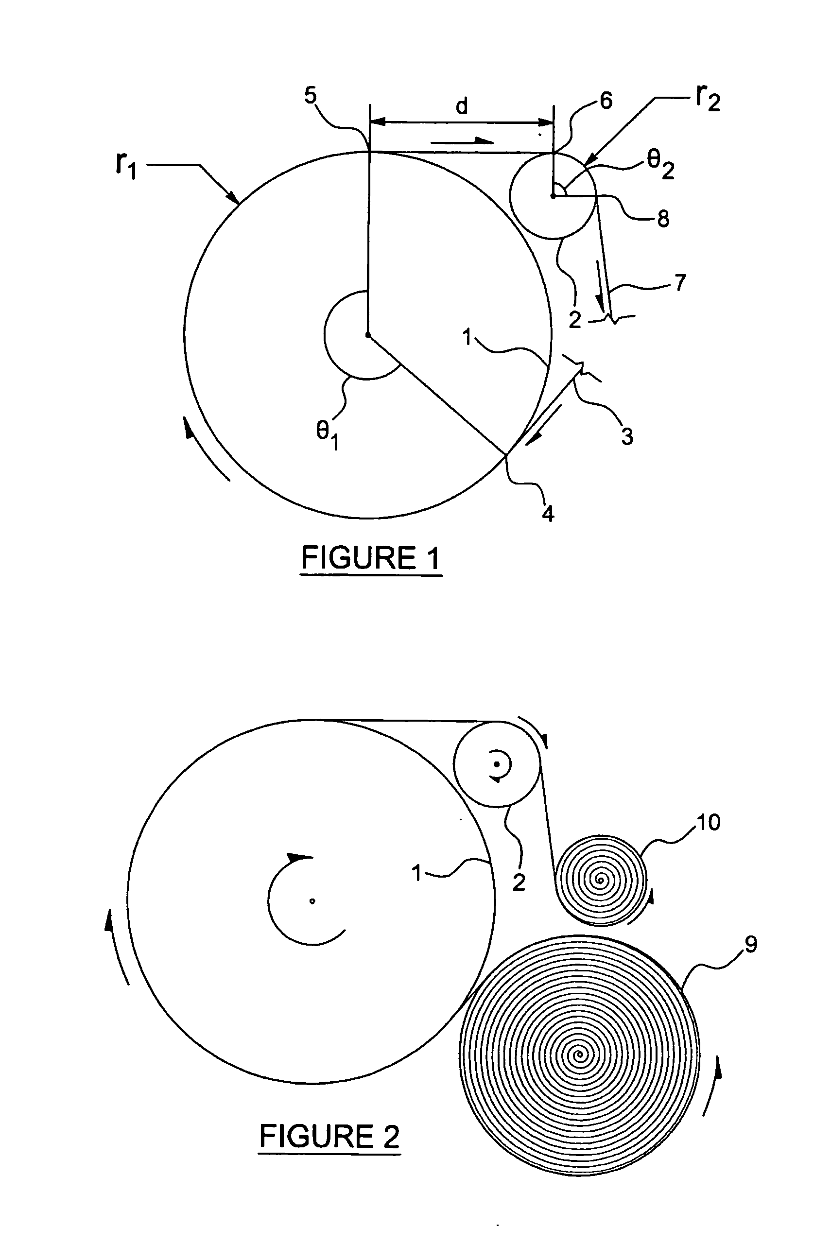
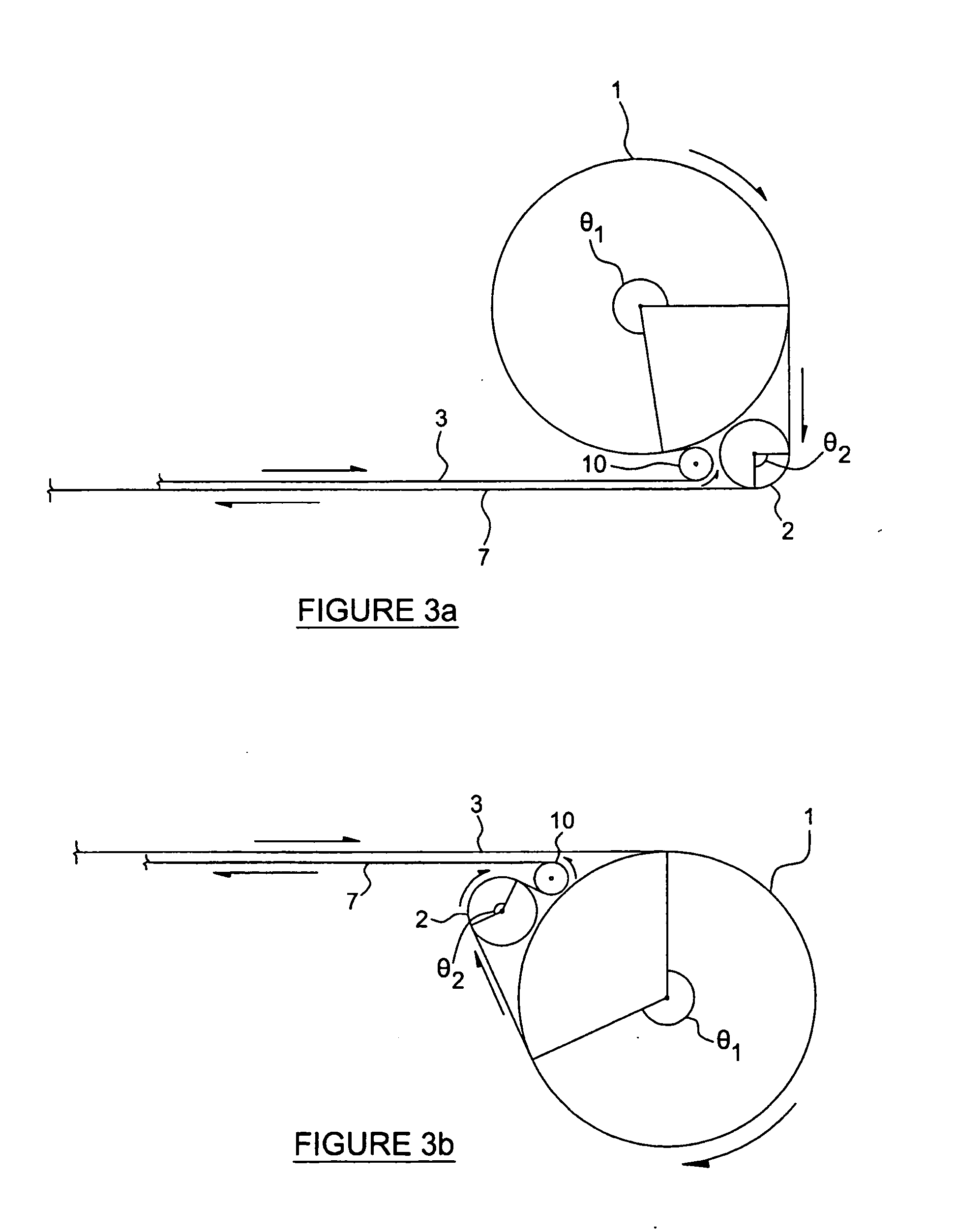
[0046]Preferably, the amorphous alloy ribbon is in contact with at least one guide roller proximate a selected one of the first, second or third cylinders, said guide roller having a radius that is smaller than the selected cylinder and being positioned proximate both an initial contact point and a final contact point between the ribbon and the selected cylinder to maximize said contact angle of said selected cylinder.
[0116]a controller for controlling torque of said motor shaft to increase or reduce a tensile stress in the amorphous ribbon.

Problems solved by technology

Properties obtained at values above this field, even if they are good, will require excessive exciting power thus, rendering the alloy less attractive.
Additionally, iron-based amorphous alloys produce about one third of the core loss of silicon steels.
With a rapid solidification process, the production of amorphous alloys is however limited to a very thin ribbon of various widths.
Moreover, magnetic properties of amorphous alloys are highly sensitive to internal mechanical stresses.
Core loss and exciting power deteriorate in presence of random stresses in the alloy.
When annealing an amorphous alloy, increasing the annealing temperature and annealing time will eventually lead to onset crystallization of its atomic structure and lost of their sought magnetic properties.
However, furnace annealing of most iron-based amorphous magnetic alloy ribbons undesirably affects the ribbon mechanical structure.
The furnace annealing treatment weakens the alloy which becomes brittle and therefore complicates ribbon handling.
Furthermore, amorphous alloy cores remain highly sensitive to external stresses after annealing.
Overall, this known process for making a rectangular-wound-cut core distribution transformer from an amorphous alloy ribbon involves a great amount of discontinuous steps, which require a lot of time and floor space.
This contributes significantly to increase transformer costs.
Rolling-up-after-annealing of an amorphous alloy ribbon will certainly introduce some stresses in the roll, which will introduce some additional core loss.
Also, direct transfer of the annealed amorphous alloy ribbon will introduce unnecessary bending stresses which will cause increased core loss as the ribbon is not rolled up again at the same layer position in the circular core (the first outer layer becomes first inner layer and vice versa).
Rolling-up-after-annealing of amorphous alloy circular cores as described above, although simple in appearance, remains a difficult task.
The fact that the alloy becomes brittle when annealed for a significant amount of time makes it less convenient when it needs to be rolled up again around a limb of the electrical coils.
Silgailis et al. showed in Table 2 that circular cores weighing around 18 kg and annealed by their method could be unrolled and rolled up again at a speed of 0.76 meter per second without breaking the ribbon more than 18 times. Even if Silgailis et al. were able to significantly reduce the number of breaks with their annealing method, it remains unacceptable.
The task becomes more difficult when rolling up of the ribbon must be performed first on an intermediate mandrel.
Annealing-after-rolling of the core around the coils could overcome the problem, but this would require use of high temperature insulating materials in the coils which would render the transformer cost-prohibitive.
Even if rolling-up-after-annealing would avoid use of a high temperature insulating material, it was considered to be impractical due to the embrittlement of the ribbon and an annealing-after-rolling of a core incorporating a high temperature resistant insulation was rather adopted as reported in articles such as: “Induction Accelerator Development for Heavy Ion Fusion”, L. L. Reginato, IEEE Proceedings of the 1993 Particle Accelerator Conference, vol.
Production of circular core distribution transformers made with rolling-up-after-annealing of field furnace annealed amorphous alloy ribbon cores is impractical due to embrittlement of the alloy and therefore manufacturers are building field-furnace annealing rectangular-wound-cut core design as described above.
Thermal embrittlement of iron-based amorphous alloys induced by thermal annealing has been a recurring problem for a long time as recently stated by Kumar and al. in an article entitled: “Thermal embrittlement of Fe-based amorphous ribbons” published in 2008 in Journal of Non-Crystalline Solids, vol.
Because the embrittlement an iron-based amorphous alloy is a TTT phenomenon during annealing, the degree of ductility of an annealed ribbon must therefore be evaluated once the core magnetic properties obtained following the annealing treatment are satisfactory or within expected results, otherwise the annealing treatment is incomplete and the degree of ductility is misleading.
However, there is a limit in trying to shorten the annealing time due to a limit in heat transfer capacity within the core.
The structural relaxation is considered as an unavoidable consequence of stress relief annealing, which is believed to be responsible for the embrittlement of the ribbon.
However, no detailed information is disclosed on the configuration of the strip in the heat-treating and cooling zones other than optionally allowing the strip to cool on the mandrel.
However, the resulting core loss is not clearly disclosed and no reference is made on the exciting power.
This feeding rate range is far too slow if one wants to render this process profitable.
Too many annealing setups, labour and floor space would be required which increase costs.

Method used


Image

  • System  and method for treating an amorphous alloy ribbon
  • System  and method for treating an amorphous alloy ribbon
  • System  and method for treating an amorphous alloy ribbon

Examples


example 1

[0208]Material: Metglas 2605SA1

[0209]Ribbon feeding rate: 2.0 meters / sec

[0210]Ribbon applied tensile stress: 100 MPa

[0211]No pre-heating

[0212]Treatment temperature: 480° C.

[0213]Natural bending radius after treatment: between 3.0″ to 3.5″

[0214]Ribbon rolled up tensile stress: 5 MPa

[0215]Core weight: 1.04 kg (excluding hub)

[0216]Core inner diameter: 5.80 inches (excluding hub)

[0217]Core outer diameter: 6.83 inches

[0218]Core loss @ 1.3 Tesla, 60 Hz: 0.20 W / kg

[0219]Exciting power @ 1.3 Tesla, 60 Hz: 1.76 VA / kg

[0220]Peak magnetic field @ 1.3 Tesla, 60 Hz: 80 A / m

[0221]B80: 1.3 Tesla

[0222]B80 / Bsat: 0.83

example 2

[0223]Material: Metglas 2605SA1

[0224]Ribbon feeding rate: 5.0 meters / sec

[0225]Ribbon applied tensile stress: 100 MPa

[0226]Pre-heating angle θ3: near 180 degrees

[0227]Pre-heating roller temperature: 485° C.

[0228]Treatment temperature: 485° C.

[0229]Natural bending radius after treatment: between 3.0″ to 3.5″

[0230]Ribbon rolled up tensile stress: 5 MPa

[0231]Core weight: 1.04 kg (excluding hub)

[0232]Core inner diameter: 5.80 inches (excluding hub)

[0233]Core outer diameter: 6.83 inches

[0234]Core loss @ 1.3 Tesla, 60 Hz: 0.20 W / kg

[0235]Exciting power @ 1.3 Tesla, 60 Hz: 2.37 VA / kg

[0236]Peak magnetic field @ 1.3 Tesla, 60 Hz: 97 A / m

[0237]B80: 1.27 Tesla

[0238]B80 / Bsat: 0.81

example 3

[0239]Material: Metglas 2605HB1

[0240]Ribbon feeding rate: 2.0 meters / sec

[0241]Ribbon treatment applied tensile stress: 75 MPa

[0242]Treatment temperature: 455° C.

[0243]No pre-heating

[0244]Natural bending radius after treatment: between 3.0″ to 3.5″

[0245]Ribbon rolled up tensile stress: 5 MPa

[0246]Core weight: 1.04 kg (excluding hub)

[0247]Core inner diameter: 5.80 inches (excluding hub)

[0248]Core outer diameter: 6.83 inches

[0249]Core loss @ 1.3 Tesla, 60 Hz: 0.14 W / kg

[0250]Exciting power @ 1.3 Tesla, 60 Hz: 0.19 VA / kg

[0251]Peak magnetic field @ 1.3 Tesla, 60 Hz: 6.6 A / m

[0252]Core loss @ 1.4 Tesla, 60 Hz: 0.18 W / kg

[0253]Exciting power @ 1.4 Tesla, 60 Hz: 0.35 VA / kg

[0254]Peak magnetic field @ 1.3 Tesla, 60 Hz: 16.2 Nm

[0255]Core loss @ 1.5 Tesla, 60 Hz: 0.22 W / kg

[0256]Exciting power @ 1.5 Tesla, 60 Hz: 1.56 VA / kg

[0257]Peak magnetic field @ 1.3 Tesla, 60 Hz: 80 A / m

[0258]B80: 1.5 Tesla

[0259]B80 / Bsat t: 0.91


PUM

PropertyMeasurementUnit
speedsaaaaaaaaaa
temperatureaaaaaaaaaa

Abstract

A method and a system for continuously in-line annealing a forwarding ferromagnetic amorphous alloy ribbon in a curved shape to improve its magnetic properties without causing the ribbon to become brittle and which operates at significant high ribbon feeding rates. The amorphous alloy ribbon is fed forward, tensioned and guided along a path at a preset feeding rate and is heated at a point along the path at a rate greater than 103° C. / sec to a temperature to initiate a thermal treatment. Then the ribbon is initially cooled at a rate greater than 103° C. / sec until the thermal treatment ends. During the thermal treatment, a series of mechanical constraints is applied on the ribbon until the amorphous alloy ribbon adopts a specific shape at rest after the thermal treatment is ended. After the initial cooling, the amorphous alloy ribbon is subsequently cooled at a sufficient rate to a temperature that will preserve the specific shape.

Description

FIELD OF THE INVENTION[0001]The present invention generally relates to amorphous materials. More particularly, it relates to a system and method for treating an amorphous alloy ribbon. More particularly, it also relates to a system and method for producing a magnetic core from a treated ductile amorphous alloy ribbon rolled up on a mandrel.BACKGROUND OF THE INVENTION[0002]Iron-based amorphous alloys are sought for their soft magnetic properties in applications such as the manufacturing of distribution transformer cores, pulse power cores, and other item. Iron-based alloys in this document are mainly iron alloyed with various small percentages of other metals. They are manufactured by continuous rapid solidification of a stream of molten alloy cast at speeds approaching 100 km per hour. With casting cooling rates on the order of 106° Celsius / second, the alloy atomic structure is solidified in a non-crystalline state (amorphous). With the proper atomic composition, amorphous alloy rib...

Claims


Application Information

Patent Timeline
Patent Type & Authority Applications(United States)
IPC IPC(8): H01F7/00F28D21/00H01F41/02C22C45/02C21D8/02
CPCC21D8/1272Y10T29/5187C21D2201/03C22C38/02C22C45/02C21D8/125H01F27/00H01F41/02C21D8/0205F28D21/00H01F7/00F28D11/02H05B6/105H05B6/145Y10T29/49071C21D9/573C21D9/56H01F27/002H01F27/25H01F27/2876H01F27/30H01F27/325H01F30/16H01F41/022H01F41/071H01F41/098H01F27/06Y02P10/25H01F1/14775H01F7/0215H01F41/0226
Inventor FRANCOEUR, BRUNOCOUTURE, PIERRE
Owner HYDRO QUEBEC CORP
Why Eureka
Eureka Blog
Learn More