Thermodynamically shielded solar cell
a solar cell and thermal shielding technology, applied in the field of solar cells, can solve the problems of low efficiency of solar cells and inability to compete with fossil fuels, and achieve the effects of minimising radiative losses, reducing conductive heat loss, and reducing solar energy consumption
- Summary
- Abstract
- Description
- Claims
- Application Information
AI Technical Summary
Benefits of technology
Problems solved by technology
Method used
Image
Examples
embodiment 10
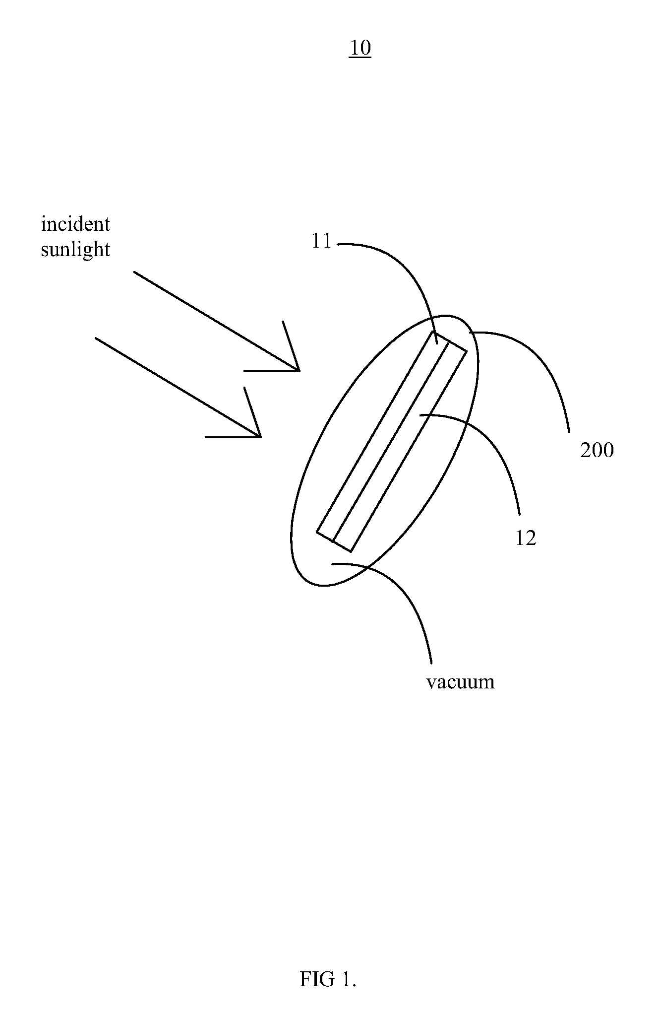
[0037]FIG. 1 shows a very simple embodiment of the inventive solar cell embodiment 10. A tandem solar cell with semiconductor layers 11 and 12 is enclosed in a casing or a membrane 200 that is transparent to solar light.
[0038]The semiconductor layers 11 and / or 12 may be composed of any material capable of photoelectric effect. For example the semiconductor layer 11, or any subsequent layer mentioned in this application (12, 13, 14, 15, 16, 17, layer 1, layer 2) may contain Si (Silicon), polycrystalline silicon, thin-film silicon, amorphous silicon, Ge (Germanium), GaAs (Gallium Arsenide), GaAlAs (Gallium Aluminium Arsenide), GaAlAs / GaAs, GaP (Gallium Phosphide), InGaAs (Indium Gallium Arsenic), InP (Indium phosphide), InGaAs / InP, GaAsP (Gallium Arsenic Phosphide) GaAsP / GaP, CdS (Cadmium Sulphide), CIS (Copper Indium Diselenide), CdTe (Cadmium Telluride), InGaP (Indium Gallium Phosphide) AlGaInP (Aluminum Gallium Indium Phosphide), InSb (Indium Antimonide), CIGS (Copper Indium / Galliu...
embodiment 20
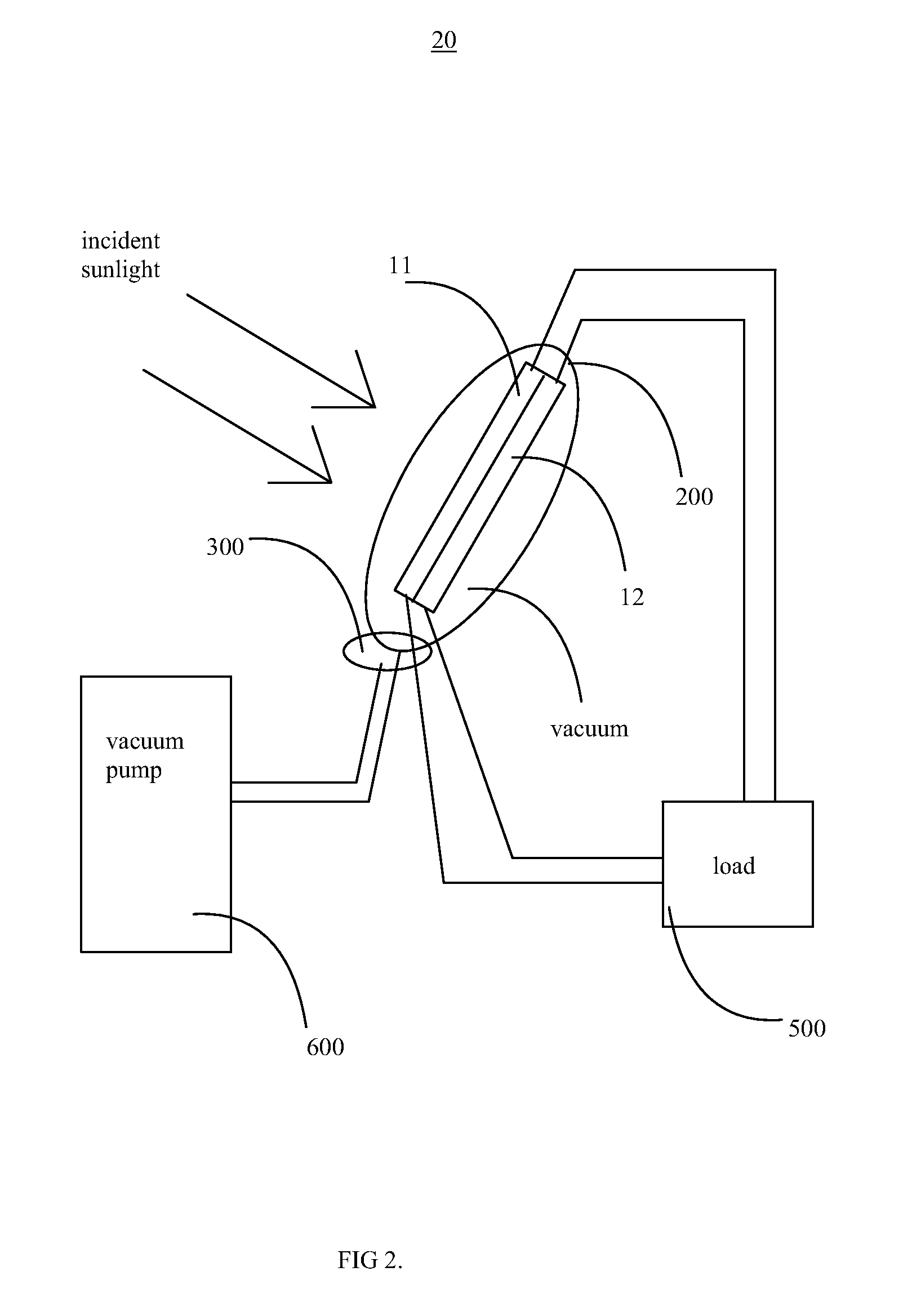
[0050]FIG. 2 shows an embodiment 20 of the solar cell in accordance with the invention, where the solar cell is used to power a load 500. The load 500 can be any device requiring electricity as energy, a energy storage device such as a battery or the electric grid itself. The photocurrent is collected from the semiconductor materials 11 and 12 to the load by electrical wires. Ideally the wires for the photocurrent collection should be made small and insulated, to minimise conductive and / or convective losses.
[0051]In some embodiments the casing and / or membrane 200 also incorporates a vent 300. In some embodiments the vent 300 may also incorporate a thermostat. In most embodiments of the invention the solar cell is similar to embodiment 10 explained before, and to save repetition it is noted that all embodiments 10, 20, 30, 40, 50, 60 and 70 may be freely permuted and changed and features from one embodiment to the other can be transferred in accordance with the invention.
[0052]A vacu...
embodiment 30
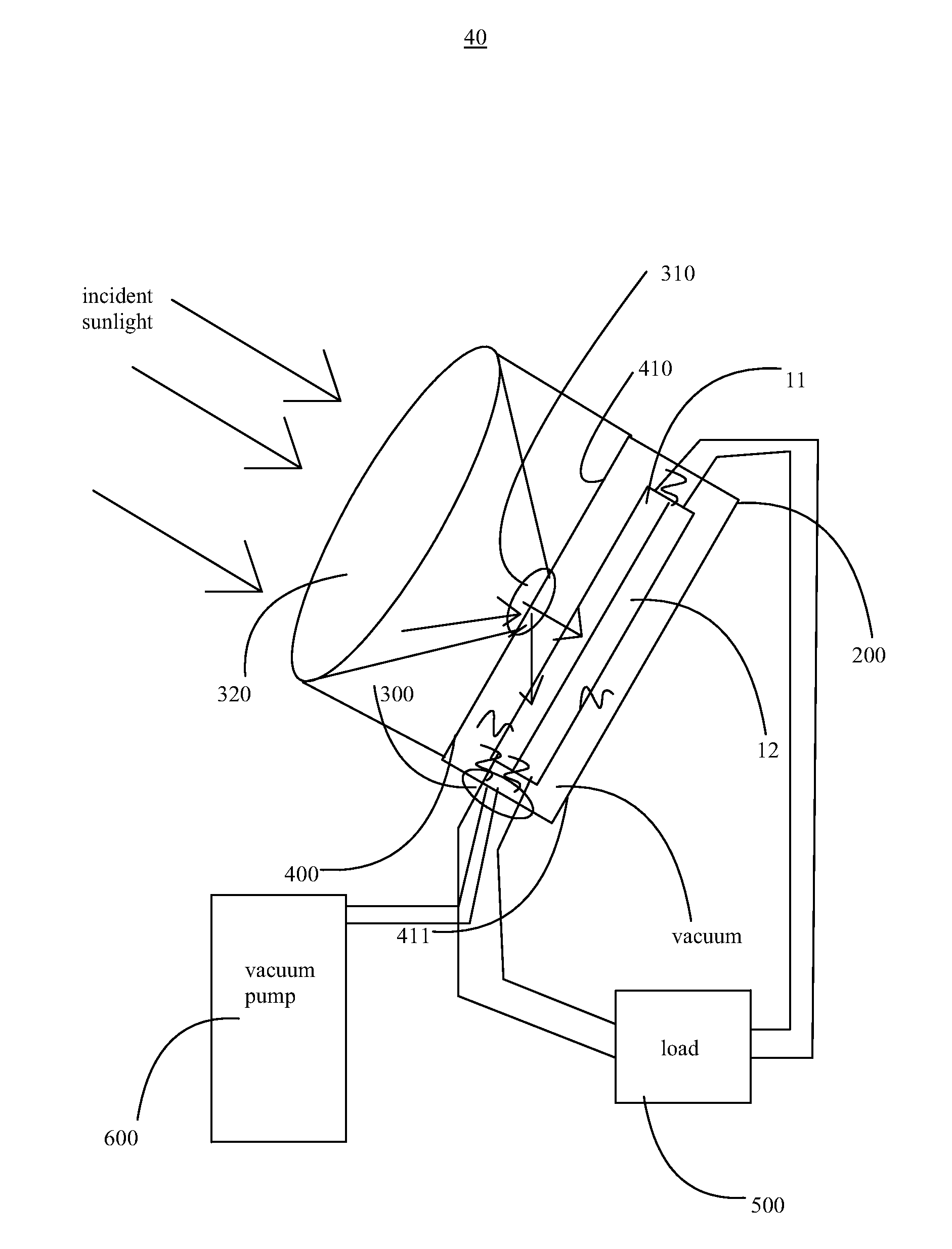
[0058]FIG. 3 displays an embodiment 30 of the inventive solar cell, where optical concentration devices and radiative, conductive and convective shielding are used to maximise photon entrapment in the casing and / or membrane 200.
[0059]The solar cell system comprises a focusing element 320, such as a lens or a mirror that is used to focus the incident solar light to a smaller area, thereby increasing flux in that area. The focused solar light is directed to an opening into the casing 200 for housing the photovoltaic cell system with semiconductor materials 11, 12. In some embodiments this opening may be installed with a ray diverging element 310 that spreads the solar light from the focused area to a wider area as the solar light passes through it. In some embodiments the diverging element 310 is a prism, mirror or a lens. Typically the elements 320, 310 are arranged so that a maximum photon collection area is obtained, and the photons are spread out across the entire surface of the p...
PUM
 Abstract
Description
Claims
Application Information
 - R&D
- Intellectual Property
- Life Sciences
- Materials
- Tech Scout
- Unparalleled Data Quality
- Higher Quality Content
- 60% Fewer Hallucinations
Browse by: Latest US Patents, China's latest patents, Technical Efficacy Thesaurus, Application Domain, Technology Topic, Popular Technical Reports.
© 2025 PatSnap. All rights reserved.Legal|Privacy policy|Modern Slavery Act Transparency Statement|Sitemap|About US| Contact US: help@patsnap.com


