Metal member manufacturing method and metal member
a metal member and manufacturing method technology, applied in the field of metal member manufacturing method and metal member, can solve the problems of difficult to reduce this pore size, the reconstruction of such functions will become an extremely important issue, and the difficulty of daily life caused by deterioration or loss of functions of various organs, etc., to achieve excellent biocompatibility and suppress the elution of nickel ions
- Summary
- Abstract
- Description
- Claims
- Application Information
AI Technical Summary
Benefits of technology
Problems solved by technology
Method used
Image


Examples
example 2
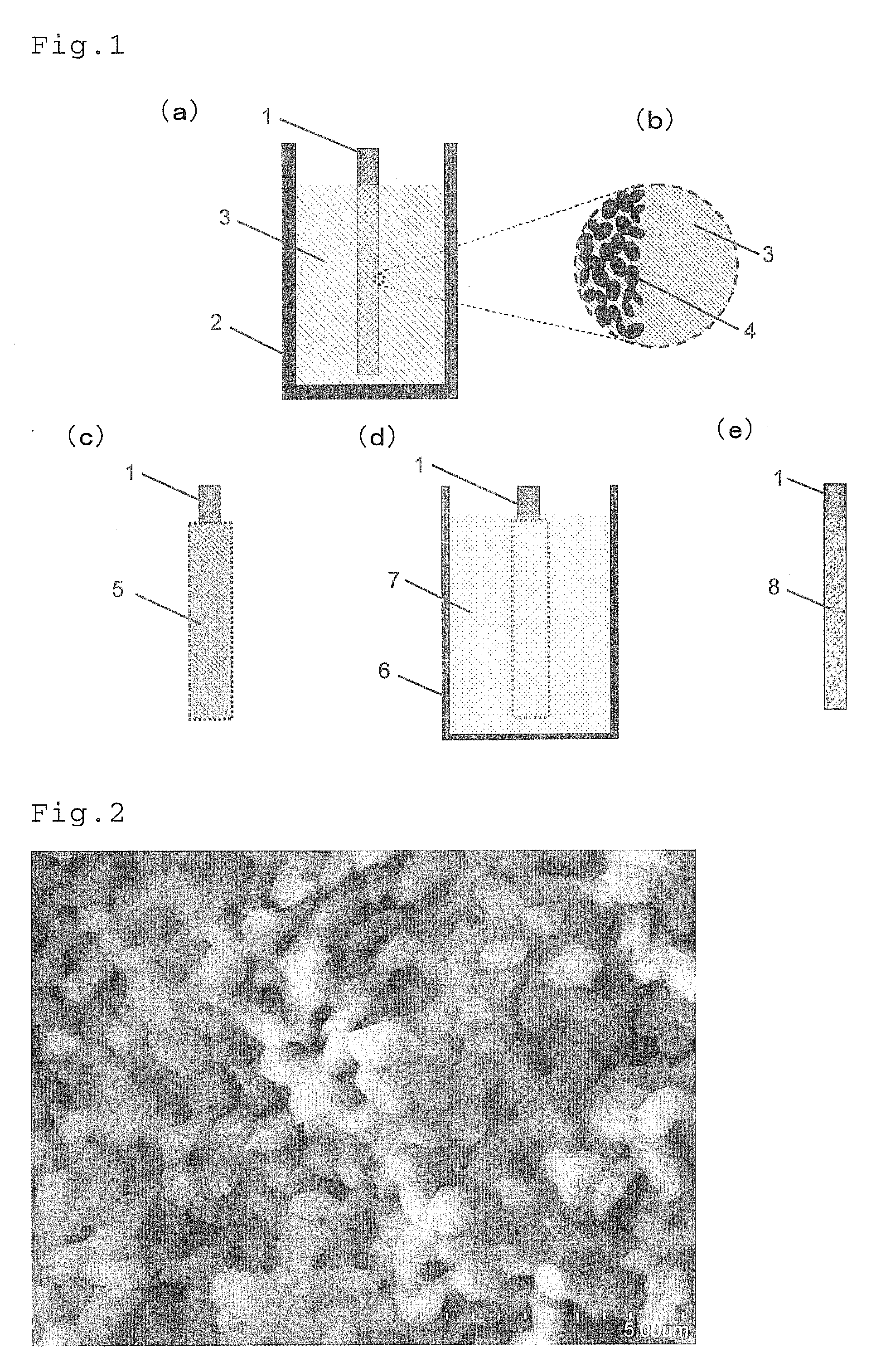
[0045]Approximately 30 g of Cu50Ti30Ag20 of which composition had a Cu:Ti:Ag atomic ratio of 50:30:20 was produced in a pure argon gas atmosphere by the arc melting method. After mechanically pulverizing this master alloy, approximately 5 g of the master alloy was placed in a quartz nozzle measuring 7 mm in inside diameter and 70 mm in length, from which a cylindrical metallic material 1 measuring approximately 1 mm in diameter and 50 mm in length was fabricated using the copper mold casting technique in a pure argon gas atmosphere.
[0046]Next, 10 g of pure magnesium was placed in a graphite crucible 2 having an inside diameter of 30 mm and a depth of 50 mm and dissolved by high-frequency melting in the pure argon gas atmosphere to produce a magnesium molten metal bath 3 while regulating output so as to maintain a liquid temperature of 700° C. This temperature must be regulated to a temperature lower than an approximately 950° C. minimum value of a liquidus temperature within a range...
example 3
[0049]Approximately 30 g of Cu70Ti30 of which composition had a Cu:Ti atomic ratio of 7:3 was produced in a pure argon gas atmosphere by the arc melting method. After mechanically pulverizing this master alloy, approximately 5 g of the master alloy was placed in a quartz nozzle measuring 7 mm in inside diameter and 70 mm in length, from which a cylindrical metallic material 1 measuring approximately 1 mm in diameter and 50 mm in length was fabricated using the copper mold casting technique in a pure argon gas atmosphere.
[0050]Next, approximately 10 g of pure magnesium was placed in a graphite crucible 2 having an inside diameter of 30 mm and a depth of 50 mm and dissolved by high-frequency melting in the pure argon gas atmosphere to produce a magnesium molten metal bath 3 while regulating output so as to maintain a liquid temperature of 700° C. This temperature must be regulated to a temperature lower than an 868° C. minimum value of a liquidus temperature within a range of composit...
example 4
[0053]Approximately 30 g of Cr30Co70 of which composition had a Cr:Co atomic ratio of 3:7 was produced in a pure argon gas atmosphere by the arc melting method. After mechanically pulverizing this master alloy, approximately 6 g of the master alloy was placed in a quartz nozzle measuring 7 mm in inside diameter and 70 mm in length, from which a cylindrical metallic material 1 measuring approximately 1 mm in diameter and 50 mm in length was fabricated using the copper mold casting technique in a pure argon gas atmosphere.
[0054]Next, approximately 15 g of pure cerium was placed in a graphite crucible 2 having an inside diameter of 30 mm and a depth of 50 mm and dissolved by high-frequency melting in the pure argon gas atmosphere to produce a cerium molten metal bath 3 while regulating output so as to maintain a liquid temperature of 900° C. This temperature must be regulated to a temperature lower than a 1395° C. minimum value of a liquidus temperature within a range of compositional ...
PUM
| Property | Measurement | Unit |
|---|---|---|
| Temperature | aaaaa | aaaaa |
| Metallic bond | aaaaa | aaaaa |
| Melting point | aaaaa | aaaaa |
Abstract
Description
Claims
Application Information
 - R&D
- Intellectual Property
- Life Sciences
- Materials
- Tech Scout
- Unparalleled Data Quality
- Higher Quality Content
- 60% Fewer Hallucinations
Browse by: Latest US Patents, China's latest patents, Technical Efficacy Thesaurus, Application Domain, Technology Topic, Popular Technical Reports.
© 2025 PatSnap. All rights reserved.Legal|Privacy policy|Modern Slavery Act Transparency Statement|Sitemap|About US| Contact US: help@patsnap.com