
Label-free cellular manipulation and sorting via biocompatible ferrofluids

Active Publication Date: 2012-09-20
YALE UNIV
View PDF3 Cites 16 Cited by
  • Summary
  • Abstract
  • Description
  • Claims
  • Application Information

AI Technical Summary

Benefits of technology

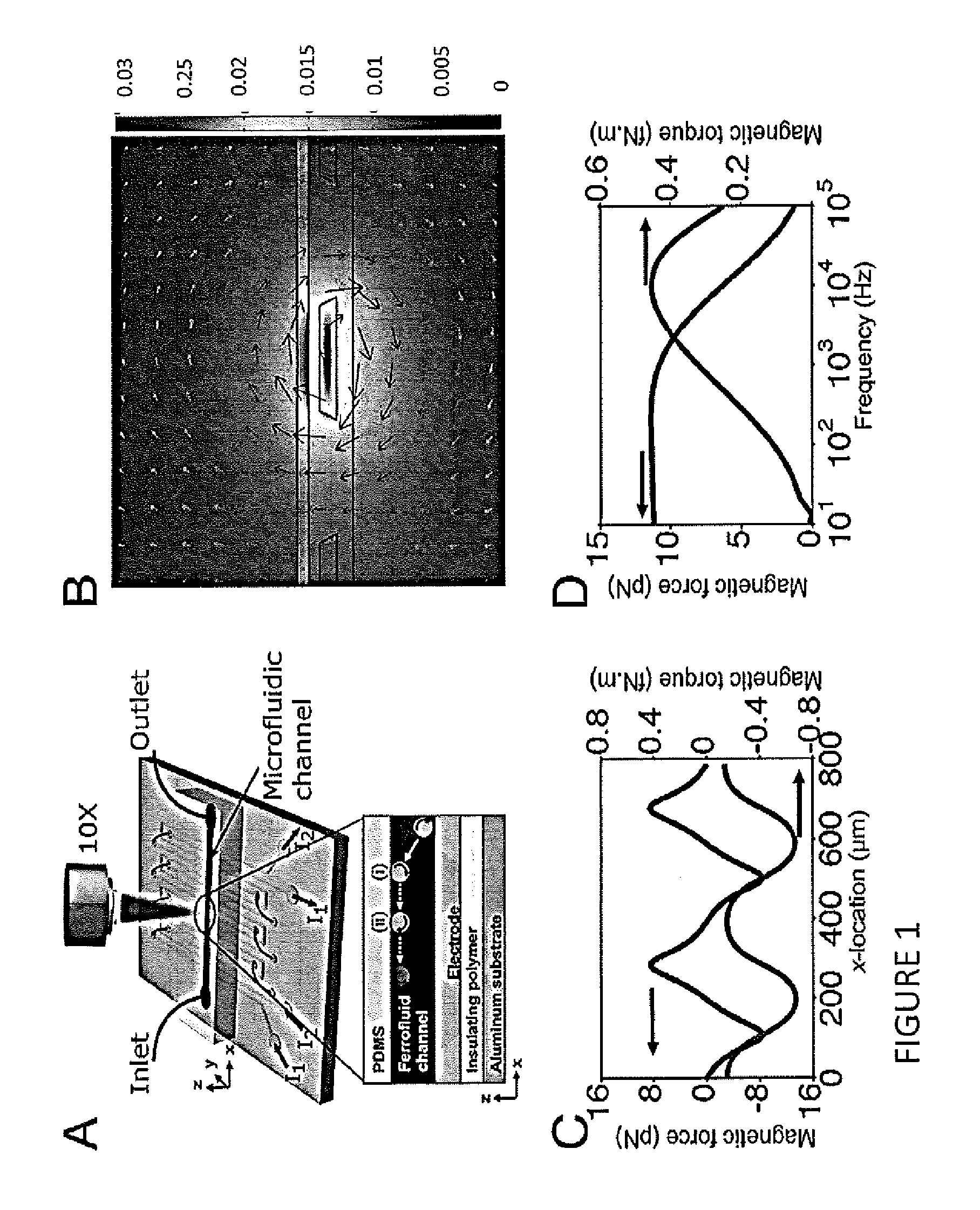
[0004]A device for separating a sample of particles suspended in a biocompatible ferrofluid is described. The device includes a microfluidic channel having a sample inlet, at least one output, and a length between the sample inlet and the at least one output, wherein a sample can be added to the sample inlet and flow along the length to the at least one outlet. The device includes a plurality of electrodes, wherein the microfluidic channel length transverses the plurality of electrodes, and further includes a power source for applying a current to the plurality of electrodes to create a magnetic field pattern along the length of the microfluidic channel. In one embodiment, the spacing between electrodes is gradually increased. In another embodiment, the spacing between electrodes is gradually decreased. In another embodiment, the plurality of electrodes comprise at least one electrode layer. In another embodiment, the plurality of electrodes comprises a plurality of electrode layers. In another embodiment, the plurality of electrode layers is in a substantially orthogonal pattern. In another embodiment, the plurality of electrodes comprises a pattern of concentric circles. In another embodiment, the walls of the microfluidic channel length include a pocketed, a ridged, a grooved, a trenched or a sloped region. In another embodiment, the microfluidic channel length transverses at least a portion of the plurality of electrodes at an angle between about 1-90 degrees. In another embodiment, the particles are living cells.
[0005]Also described is a system for separating at least one target from a sample suspended in a biocompatible ferrofluid. The system includes a microfluidic channel having a sample inlet, at least one output, and a length between the sample inlet and the at least one output, wherein a sample can be added to the sample inlet and flow along the length to the at least one outlet. The system also includes a plurality of electrodes, wherein the microfluidic channel length transverses the plurality of electrodes, and further generates a magnetic field pattern along the length

Problems solved by technology

However, most existing methods have been unable to reliably achieve fast speed, high throughput and resolution, simultaneously with low costs (Dufresne et al., 1998, Rev Sci Instrum 69:1974-1977; Kremser et al., 2004, Electrophoresis 25:2282-2291; Cabrera et al., 2001, Electrophoresis 22:355-362).
Optical tweezers offer high resolution and sensitivity for manipulating single cells, although such manipulation may cause sample heating (Liu et al., 1995, Biophys J 68:2137-2144), and is typically limited to a very small area (Ashkin et al., 1987, Science 235:1517-1520).
However, the downside of this technique is the lengthy incubation times and wash cycles, and the difficulty of removing the label post priori (Gijs 2004, Microfluidics Nanofluidics 1:22-40).
However, high throughput with this device requires high-resolution lithography on a large area, keeping the cost per device high.

Method used


Image

  • Label-free cellular manipulation and sorting via biocompatible ferrofluids
  • Label-free cellular manipulation and sorting via biocompatible ferrofluids
  • Label-free cellular manipulation and sorting via biocompatible ferrofluids

Examples


experimental examples

[0060]The invention is now described with reference to the following Examples. These Examples are provided for the purpose of illustration only and the invention should in no way be construed as being limited to these Examples, but rather should be construed to encompass any and all variations which become evident as a result of the teaching provided herein.

[0061]Without further description, it is believed that one of ordinary skill in the art can, using the preceding description and the following illustrative examples, make and utilize the present invention and practice the claimed methods. The following working examples therefore, specifically point out the preferred embodiments of the present invention, and are not to be construed as limiting in any way the remainder of the disclosure.

Ferrofluid Preparation

[0062]A co-precipitation method was used to synthesize cobalt-ferrite nanoparticles that were eventually incorporated into a water-based ferrofluid with a 20% solid content (K...

example 1

Ferrofluid Properties and Device Characterization

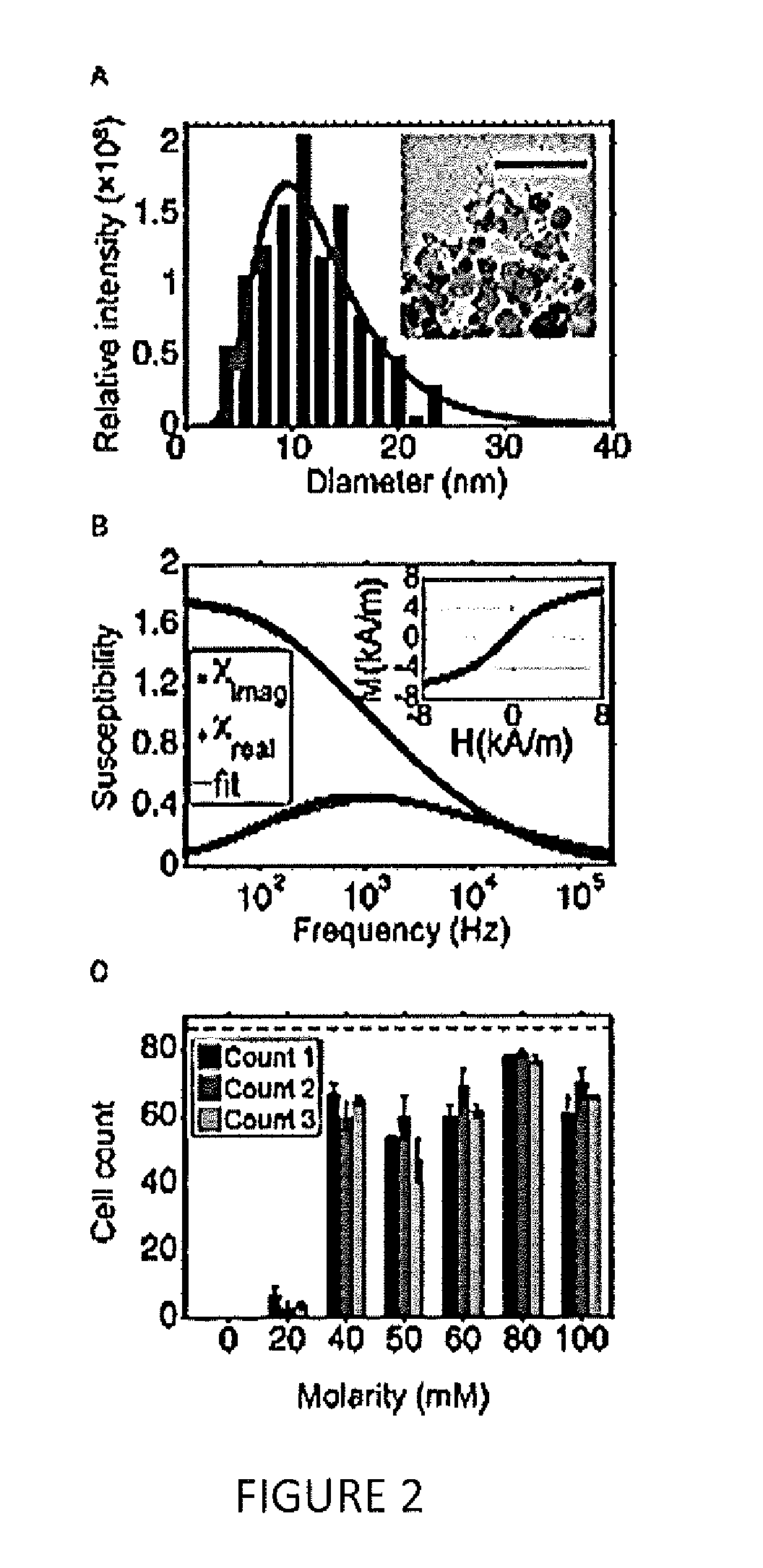
[0079]Using highly concentrated ferrofluids with live cells has traditionally proven to be a challenge, because it requires a carefully engineered colloidal system. The ferrofluid parameters that are most relevant to sustaining live cells include pH, ionic strength, and nanoparticle-surfactant combination, together with their overall and relative concentrations. Finding the right nanoparticle-surfactant combination is crucial in this regard: the ferrofluid needs to be stable at a pH of 7.4, and colloidal stability has to be maintained up to an ionic strength that can sustain live cells. One also needs to pay special attention to the size distribution of the nanoparticles within the ferrofluid. If there exist nanoparticles only a few nanometers in diameter, they could pass through the cell membrane and cause direct cytotoxicity (Scherer et al., 2005, Brazilian J Phys 45:718-727). For this reason, the present invention includes a magne...

example 2

Effects of Current Amplitute on Microparticle Speed

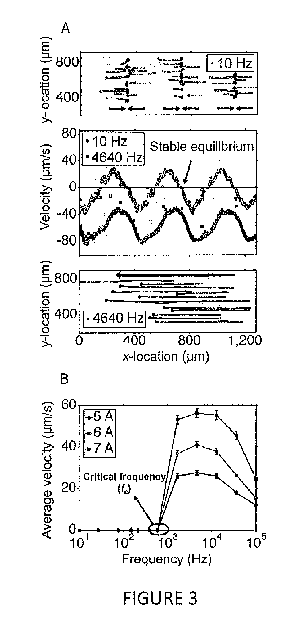
[0088]In additional experiments, the dependence of microparticle manipulation speed as a function of input current amplitude was determined. According to the calculations outlined in herein, and assuming the ferrofluid remains magnetically linear, the particle speed scales with the square of the input current. As illustrated in FIG. 6A, this assumption begins to break above 7 A peak-to-peak input current amplitude.

[0089]Electrode spacing was also varied (with electrode width fixed at 210 μm) to determine its effect on particle manipulation. A smaller electrode spacing resulted in faster average particle speeds and lower critical frequencies (FIG. 6B). This observation could be explained by noting that electrodes spaced closer reduce the local magnetic field gradient that produces the magnetic force on the microparticles; closer electrodes also pack more energy into the fundamental of the travelling wave that produces the magnetic t...


PUM


Abstract

A device for separating a sample of cells suspended in a bio-compatible ferrofluid is described. The device includes a microfluidic channel having a sample inlet, at least one outlet and a length between the same inlet and the at least one outlet, wherein a sample can be added to the sample inlet and flow along the microfluidic channel length to the at least one outlet. The device includes a plurality of electrodes and a power source for applying a current to the plurality of electrodes to create a magnetic field pattern along the microfluidic Channel length. The present invention also includes a method of using said device for separating at least one cell type.

Description

BACKGROUND OF THE INVENTION [0001]Early diagnosis of diseases involving rare cells in blood (such as metastatic cancer or low-level bacteremia) and accurate monitoring of certain genetic conditions (such as sickle cell anemia) require rapid and accurate separation, sorting, and direction of target cell types toward a sensor surface. In that regard, cellular manipulation, separation, and sorting are increasingly finding application potential within various bioassays in the context of cancer diagnosis (Dittrich et al., 2006, Nat Rev Drug Discovery 5:210-218), pathogen detection (Beyor et al., 2008, Biomed Microdevices 10:909-917), and genomic testing (Kamei et al. 2005, Biomed Microdevices 7:147-152; Cheong et al., 2008, Lab Chip 8:810-813).[0002]A variety of contactless micromanipulation methods exist, including optical tweezers (Ashkin et al., 1987, Nature 330:769-771; Chiou et al., 2005, Nature 436:370-372), dielectrophoresis (DEP) (Hughes, 2002, Electrophoresis 23:2569-2582), magn...

Claims


Application Information

Patent Timeline
IPC IPC(8): C12M1/42C12N13/00
CPCB03C1/253B03C2201/26B03C2201/18B03C1/023B03C1/288B03C1/32B03C2201/24G01N15/1023G01N15/01G01N2015/1028B01L3/502715B01L3/50273B01L3/502761B01L2200/0636B01L2200/0652B03C1/23B01L2300/06B01L2300/0848C12M47/04C12N13/00G01N2015/1006
Inventor KOSER, HUR
Owner YALE UNIV
Learn More