
Thermochemical Structuring of Matrix Components for FCC Catalysts

a technology of matrix components and catalysts, applied in the direction of catalyst activation/preparation, physical/chemical process catalysts, catalyst activation/preparation, etc., can solve the problems of high cracking activity, limited utility of catalysts, selectivity losses, etc., and achieve the effect of increasing the internal porosity of oxides

Inactive Publication Date: 2012-09-13
BASF CORP
View PDF3 Cites 17 Cited by
  • Summary
  • Abstract
  • Description
  • Claims
  • Application Information

AI Technical Summary

Benefits of technology

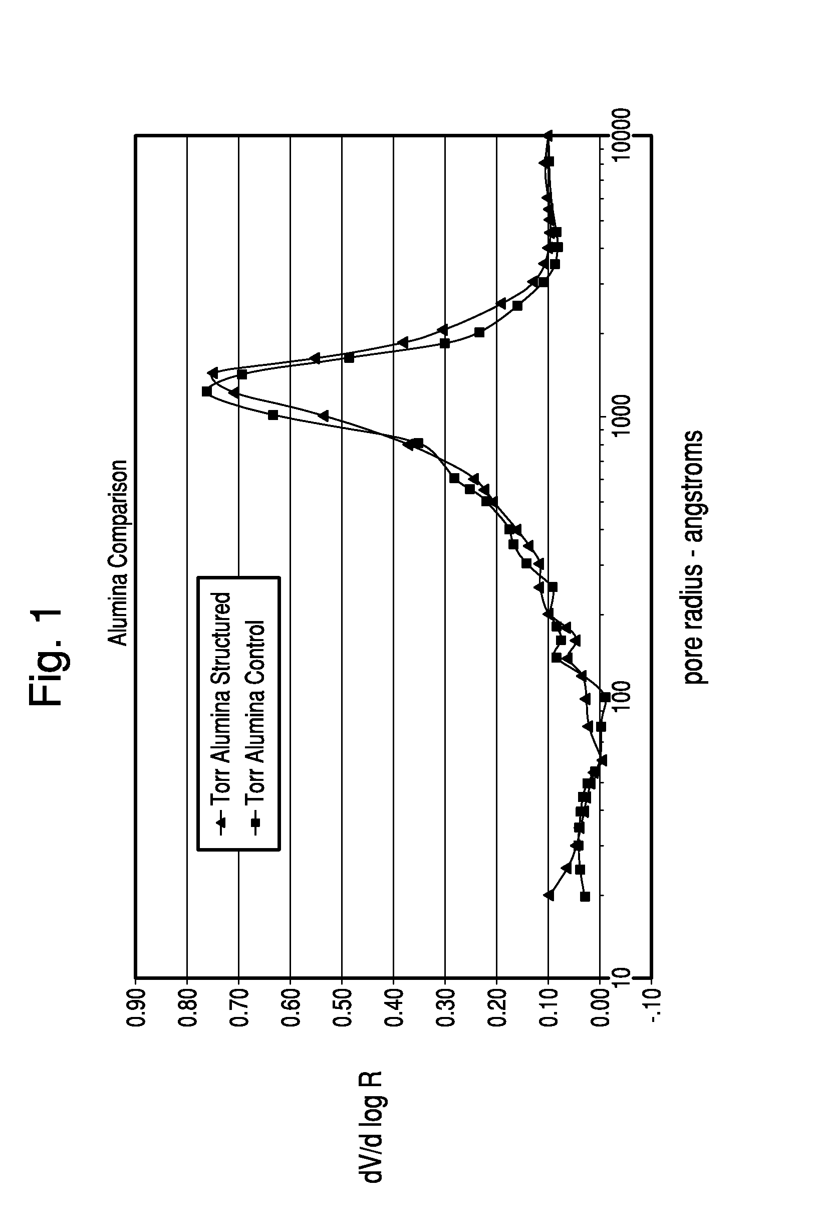
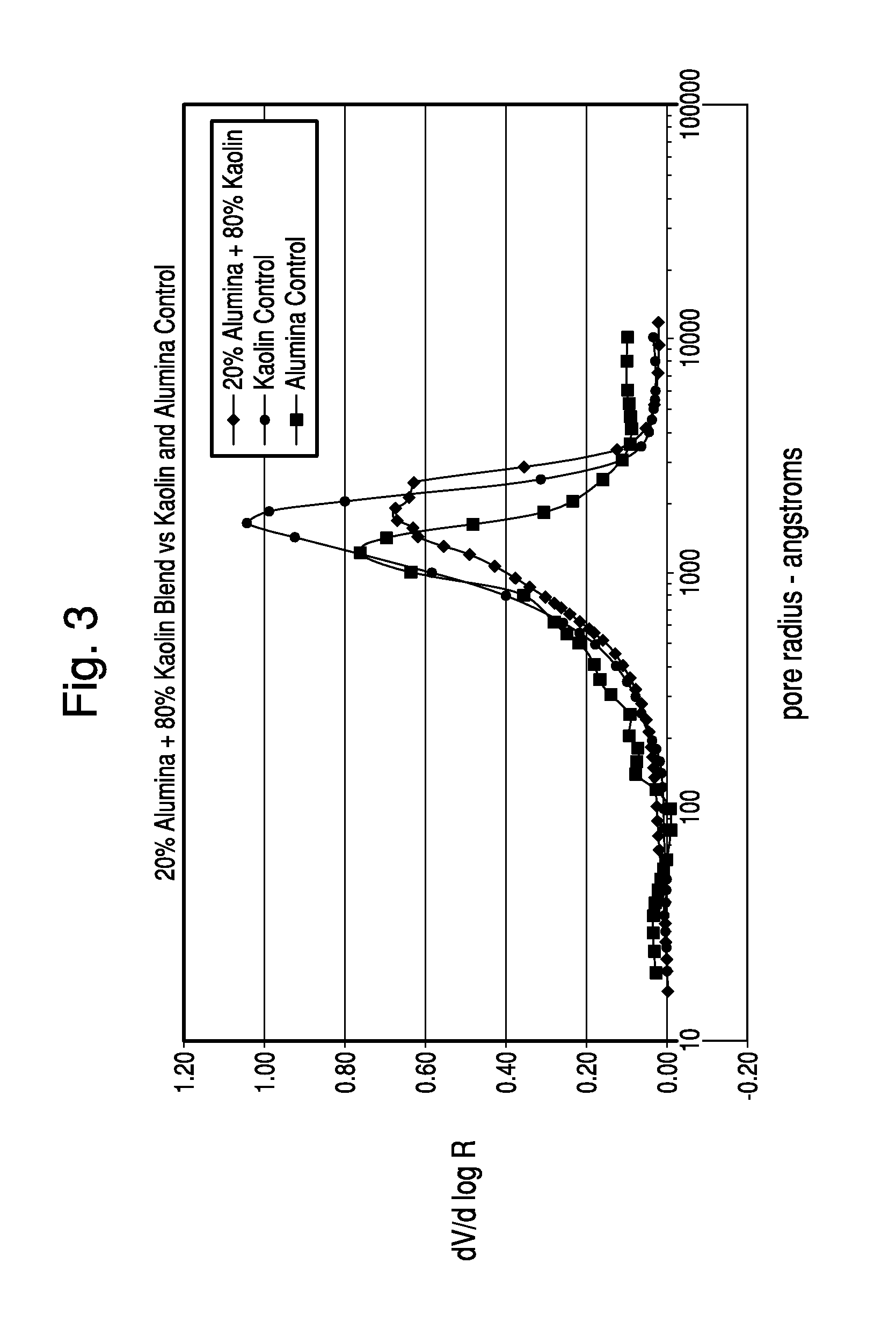
[0025]It has now been found that metallic oxides which have been used as matrix materials for FCC catalysts, when treated with small amounts of polyphosphate and then heated, are unexpectedly provided with internal structuring so as to increase the internal porosity of the oxide. Metallic oxides which can change crystalline phases upon heating when so treated, can maintain internal pore volume during the phase change and even as the hardness of the metallic oxide increases during heat treatment.

Problems solved by technology

Thus, a cracking catalyst can have outstandingly high cracking activity, but if the activity results in a high level of conversion to coke and / or gas at the expense of gasoline the catalyst will have limited utility.
For example, such a result is contrary to the prior art disclosures that low pore volumes “can lead to selectivity losses due to diffusional restrictions.”
Thus, while typical FCC catalysts formed by mechanically incorporating the zeolite within a matrix may have been more porous, the reaction time in prior art FCC risers did not yield any advantage in activity or selectivity.
Assertions made to the contrary were inconsistent with the facts and easily dismissed as self-serving.
Several of the designs do not even employ a riser, further reducing contact time to below one second.
The processing of increasingly heavier feeds in FCC type processes and the tendency of such feeds to elevate coke production and yield undesirable products have also led to new methods of contacting the feeds with catalyst.
Unfortunately, it has been found that the API gravity of the bottoms formed during short contact time (SCT) often increases after a unit revamp, leading some to suggest that the heaviest portion of the hydrocarbon feed takes longer to crack.
Metal agglomeration or sintering is a leading cause of loss of activity since the activity for metal catalyzed reaction is proportional to the exposed metal surface area.
When the metal sinters metallic surface area is lost and so is activity.
While one would expect that this precracking scenario might be advantageous for resid feeds they are unfortunately characterized for the most part as being heavily contaminated with metals such as nickel and vanadium and to a lesser extent, iron.
Loss of activity or selectivity of the catalyst may also occur if the metal contaminants such as nickel, vanadium, from the hydrocarbon feedstock, deposit onto the catalyst.
These metal contaminants are not removed by standard regeneration (burning) and contribute markedly to undesirably high levels of hydrogen, dry gas and coke and reduce significantly the amount of gasoline that can be made.
Contaminant metal levels are particularly high in certain feedstocks, especially the more abundant heavier crudes.
As oil supplies dwindle, successful economic refining of these heavier crudes becomes more urgent.
In addition to reduced amounts of gasoline, these contaminant metals contribute to much shorter life cycles for the catalyst and an unbearably high load on the vapor recovery system.
Deposited nickel and vanadium species have an intrinsic dehydrogenation activity which leads to the formation of coke and gas, two undesirable products.
Furthermore, vanadium assists in destroying the crystallinity of the sieve.
This leads to a loss of catalytic activity and to the formation of certain silica-alumina species which tend to promote the formation of coke and gas.
The increased expense of refining metal-contaminated feedstocks due to the aforementioned factors lays a heavy economic burden on the refiner.
Therefore, much effort has been spent in finding means to modify the catalyst or feedstock in such a way as to passivate the aforementioned undesirable effects of the metal contaminants.
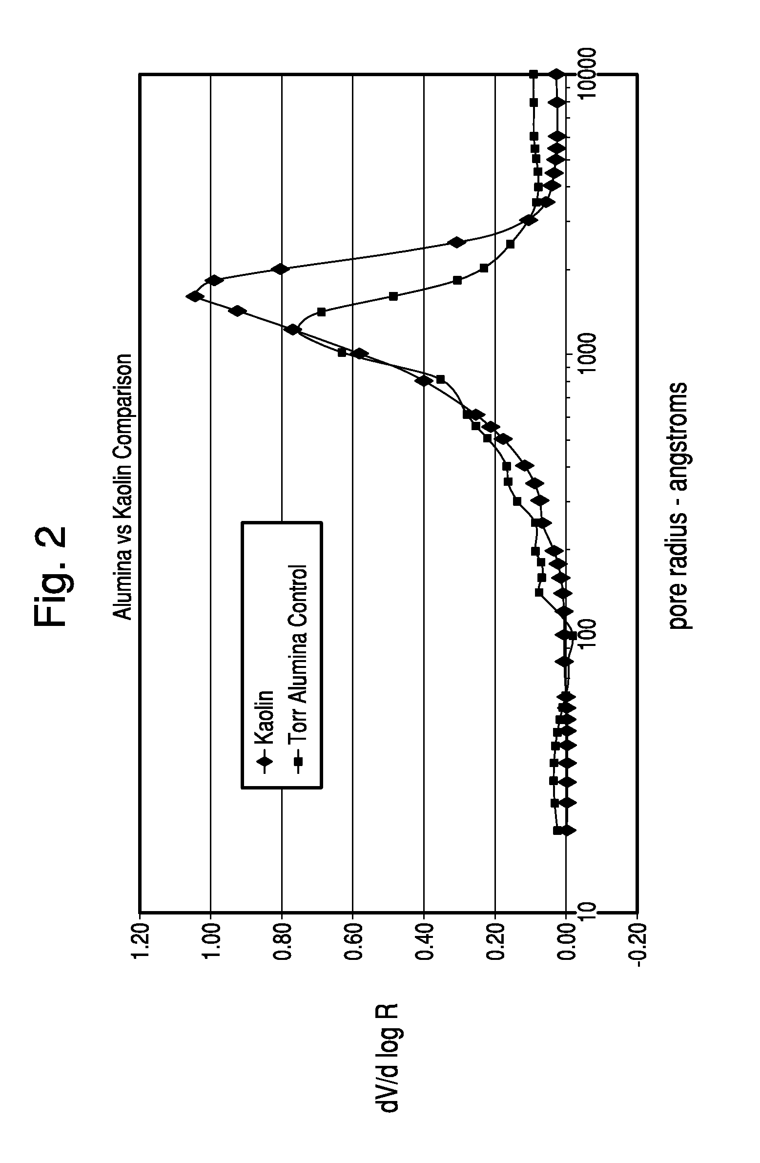
Unfortunately, the calcination of kaolin at high temperature to a mullite phase, can drastically reduce the pore volume of the matrix component.

Method used


Image

  • Thermochemical Structuring of Matrix Components for FCC Catalysts
  • Thermochemical Structuring of Matrix Components for FCC Catalysts
  • Thermochemical Structuring of Matrix Components for FCC Catalysts

Examples


example 1

[0061]In this example, the feed for a commercial calcined kaolin, used for example in a NaphthaMax® catalyst is used to demonstrate how the addition of ammonium polyphosphate liquid (11-37-0) to the spray dryer feed slurry can stabilize the mineral lattice and enhance calcined product hardness. The hydrous kaolin in this example exhibits a particle size distribution of 86 to 90% less than 1.0 micron (as measured by Sedigraph 5100 / 5120 particle size analyzer) and a BET surface area of 20.0 to 22.0 m2 / gm (Gemini 2370 surface area analyzer). 11-37-0 ammonium polyphosphate liquid was added at a rate of 0.50 weight percent P2O5 per dry ton of kaolin. The kaolin slurry concentration was in the 45 to 65% solids range.

[0062]The slurry was spray dried by a process equipped with a centrifugal atomizer. This method was selected for convenience. i.e. other drying methods would be equally effective with a goal to reduce product moisture to below 2.0 percent by weight (CEM Labwave 9000 moisture a...

example 2

[0064]The kaolin in this example is used to produce calcined intermediates for FCC catalysts and exhibited a particle size distribution of 86 to 90% less than 2.0 microns (as measured by Sedigraph 5120 particle size analyzer) and a BET surface area of 18.8 m2 / gm (Gemini 2370 surface area analyzer). 11-37-0 ammonium polyphosphate liquid was added in increasing increments of from 0.15 to 0.35 weight percent P2O5 per dry ton of kaolin. The kaolin slurry concentration to spray drying was in the 45 to 65% solids range. Apparent bulk density (ABD) is the weight per unit volume of a material, including voids that exist in the tested material. It can also be called Bulk Density and provides a measure of the “fluffiness” of a material in its supplied form. Tamped bulk density (TBD) measures the propensity of a kaolin to gradually pack more efficiently. This tendency was measured with a TAP-PACK Volumeter (ISO 787-11).

[0065]The structuring advantages brought about by the addition of polyphosp...

example 3

[0066]In this example, a dispersed kaolin feed slurry was first treated with polyphosphate, then spray dried and calcined. The spray dried product moisture was again controlled to less than 2.0% by weight but the pulverization step before heat treatment was eliminated. This approach was used to assess the benefits of polyphosphate addition in stabilizing / strengthening the cohesiveness of a fired mineral structure. Ammonium polyphosphate liquid (11-37-0) was the source of the polyphosphate treatment. The kaolin starting material was a typical dispersed hydrous slurry exhibiting a particle size distribution as measured by Sedigraph 5120 of 86% less than 2.0 microns and a BET surface area of 18.0 to 22.0 m2 / gm. The slurry was treated with ammonium polyphosphate liquid to 0.50 and 1.0 percent by weight P2O5 and then spray dried to yield a bead average particle size (APS) of 65 to 75 microns as measured by laser particle size analysis. The spray dried beads were then calcined in a muffle...


PUM

PropertyMeasurementUnit
Temperatureaaaaaaaaaa
Diameteraaaaaaaaaa
Fractionaaaaaaaaaa

Abstract

A catalyst particle which comprises a metallic oxide such as kaolin is provided with the unique structure by mixing small amounts of a polyphosphate structuring agent with the metallic oxide and heating the mixture of metallic oxide and polyphosphate to allow reaction of the structuring agent with the metallic oxide.

Description

BACKGROUND OF THE INVENTION[0001]Since the 1960's, most commercial fluid catalytic cracking catalysts have contained zeolites as an active component. Such catalysts have taken the form of small particles, called microspheres, containing both an active zeolite component and a non-zeolite component. Frequently, the non-zeolitic component is referred to as the matrix for the zeolitic component of the catalyst. The non-zeolitic component is known to perform a number of important functions, relating to both the catalytic and physical properties of the catalyst. Oblad described those functions as follows: “The matrix is said to act as a sink for sodium in the sieve thus adding stability to the zeolite particles in the matrix catalyst. The matrix serves the additional function of: diluting the zeolite; stabilizing it towards heat and steam and mechanical attrition; providing high porosity so that the zeolite can be used to its maximum capacity and regeneration can be made easy; and finally...

Claims


Application Information

Patent Timeline
IPC IPC(8): C10G11/04B01J21/16B01J29/04B01J27/18
CPCB01J21/005C10G11/05B01J29/04B01J29/084B01J29/83B01J35/002B01J35/023B01J35/1009B01J35/1019B01J35/1038B01J37/0045B01J37/06B01J37/08B01J2229/16B01J2229/37B01J2229/42B01J2229/64C10G11/04B01J27/18B01J35/30B01J35/612B01J35/40B01J35/633B01J35/615
Inventor FOLMAR, KENNETHWILLIS, MITCHELL
Owner BASF CORP
Learn More