
Drive Current Increase in Field Effect Transistors by Asymmetric Concentration Profile of Alloy Species of a Channel Semiconductor Alloy

a technology of field effect transistor and concentration profile, which is applied in the field of manufacturing of integrated circuits, can solve the problems of reducing the thickness affecting the overall performance of the integrated circuit, and reducing the maximum practical operating frequency, so as to improve the performance of transistors, improve the efficiency of the gate insulation layer, and increase the charge carrier velocity

Active Publication Date: 2012-08-02
GLOBALFOUNDRIES US INC
View PDF6 Cites 12 Cited by
  • Summary
  • Abstract
  • Description
  • Claims
  • Application Information

AI Technical Summary

Benefits of technology

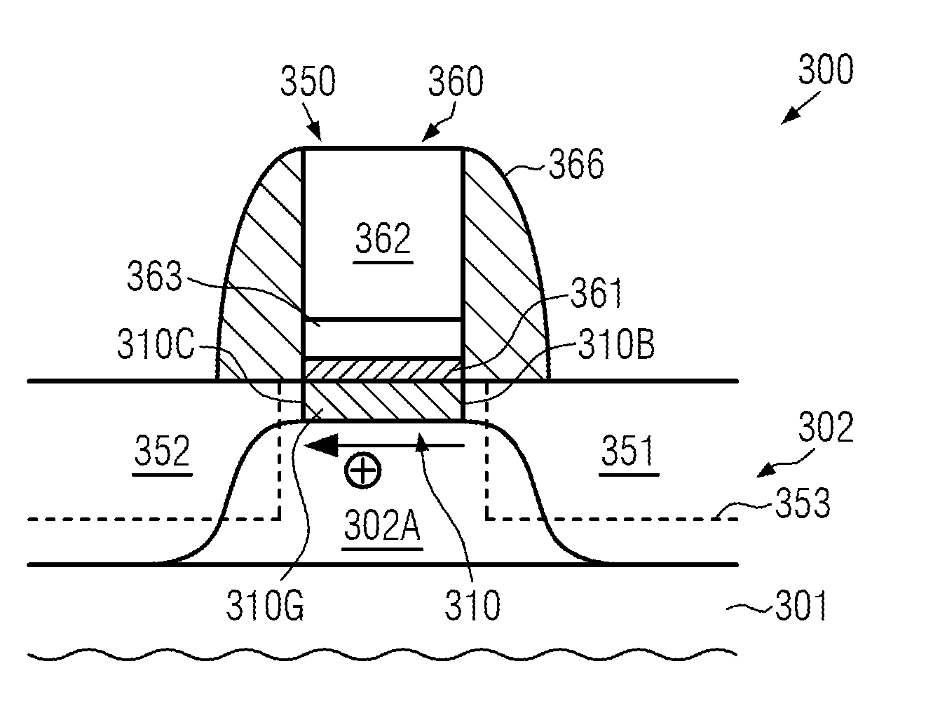
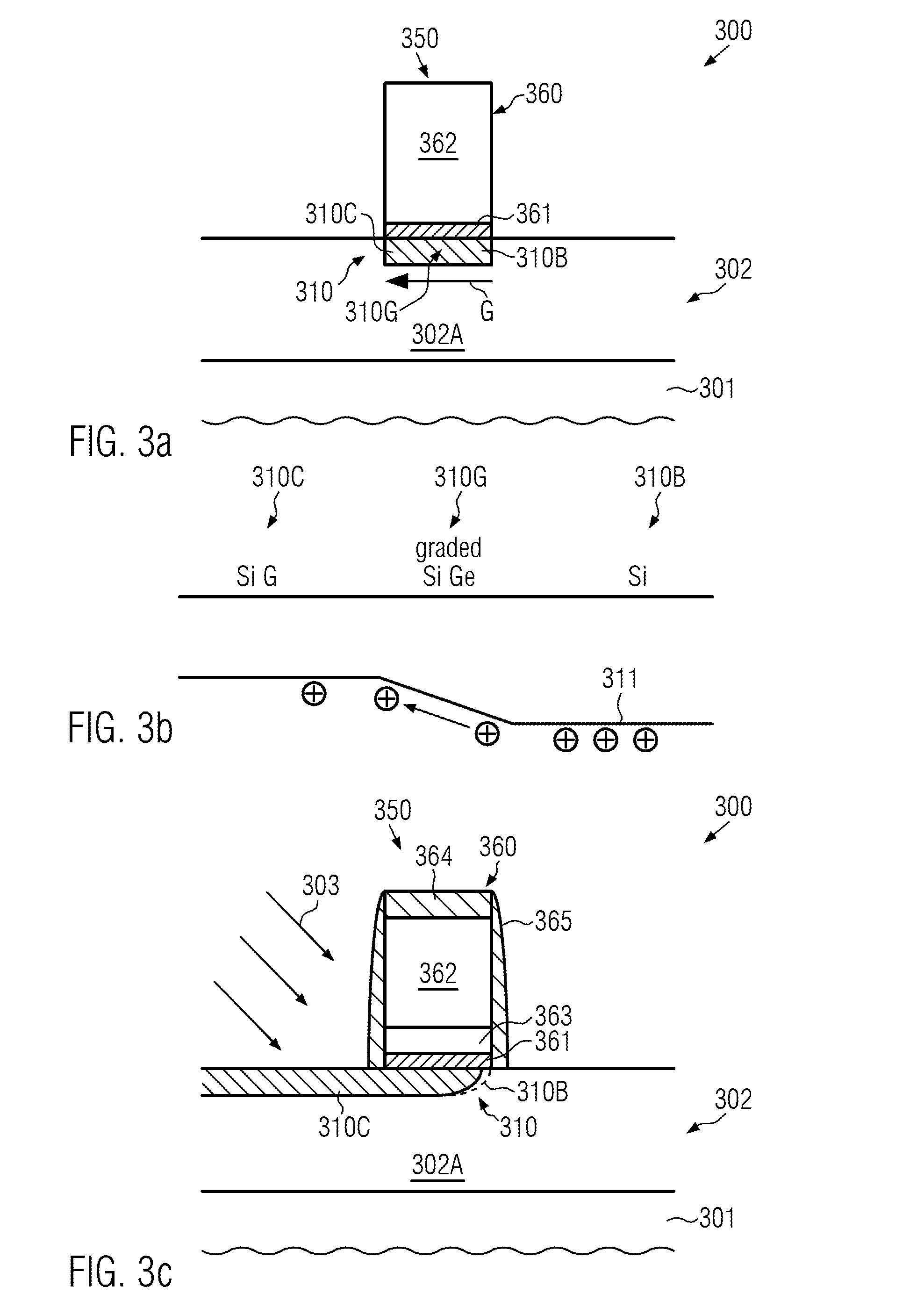
[0011]Generally, the present disclosure provides semiconductor devices and manufacturing techniques in which performance of transistors may be enhanced by implementing a gradient with respect to the band gap of the channel material, wherein the corresponding gradient is substantially oriented along the current flow direction in the channel region. According to the principles disclosed herein, it has been recognized that a gradual variation of the band gap, for instance a gradual variation of the valence band edge for a P-conductive transistor, may result in an increased charge carrier velocity for a given drain and source voltage compared to a corresponding channel region formed on the basis of a silicon base material. In some illustrative aspects disclosed herein, a corresponding gradient may be established on the basis of providing well-established semiconductor materials, such as silicon and germanium, with a varying concentration in order to obtain the desired gradient. Consequently, by appropriately adjusting the gradient with respect to the expected current flow direction, superior transistor performance may be achieved for this specific current flow direction, thereby implementing an asymmetric transistor configuration, which may be readily taken into account by appropriately designing the circuitry under consideration.

Problems solved by technology

For instance, static and dynamic leakage currents may significantly affect the overall performance of an integrated circuit, as the achievable amount of heat dissipation that is required for transistor architectures producing high dynamic and / or static leakage currents may restrict the maximum practical operating frequency.
As is well known, short channel effects may require a reduction of the thickness of the gate insulation layer which, however, may no longer be a viable option on the basis of silicon dioxide since, at a thickness of approximately 1 nm, significant leakage currents may occur, as explained above.
Since a further reduction of the thickness of well-established silicon dioxide-based gate dielectric materials may be less than desirable due to the significant increase of leakage currents, the capacitive coupling between the gate electrode and the channel region is frequently increased by providing a high-k dielectric material in sophisticated gate electrode structures.
Furthermore, since an appropriate work function of the electrode material of any such sophisticated gate electrode structures may no longer be obtained on the basis of doped polysilicon material and due to polysilicon's characteristic to form a depletion zone in the vicinity of the gate dielectric material upon operating the transistor, a metal-containing electrode material is typically formed above the high-k dielectric material.
Since typically, in complex semiconductor devices, transistors of different threshold voltage may have to be applied, thereby requiring highly complex dopant profiles in the channel region and the adjacent drain and source regions, it may be increasingly difficult to comply with these requirements on the basis of sophisticated gate electrode structures, even if different work function metal species may be provided, for instance for P-channel transistors and N-channel transistors, respectively.
It turns out, however, that the incorporation of any such materials is associated with a high risk of device failures since many process steps and integration aspects are still completely unknown in the field of forming sophisticated silicon-based semiconductor devices.
Moreover, the electronic characteristics of these materials may result in lower gate capacitance, reduced inversion layer density and thus reduced drive current compared to silicon / germanium materials.

Method used


Image

  • Drive Current Increase in Field Effect Transistors by Asymmetric Concentration Profile of Alloy Species of a Channel Semiconductor Alloy
  • Drive Current Increase in Field Effect Transistors by Asymmetric Concentration Profile of Alloy Species of a Channel Semiconductor Alloy
  • Drive Current Increase in Field Effect Transistors by Asymmetric Concentration Profile of Alloy Species of a Channel Semiconductor Alloy

Examples


Embodiment Construction

[0026]Various illustrative embodiments of the invention are described below. In the interest of clarity, not all features of an actual implementation are described in this specification. It will of course be appreciated that in the development of any such actual embodiment, numerous implementation-specific decisions must be made to achieve the developers' specific goals, such as compliance with system-related and business-related constraints, which will vary from one implementation to another. Moreover, it will be appreciated that such a development effort might be complex and time-consuming, but would nevertheless be a routine undertaking for those of ordinary skill in the art having the benefit of this disclosure.

[0027]The present subject matter will now be described with reference to the attached figures. Various structures, systems and devices are schematically depicted in the drawings for purposes of explanation only and so as to not obscure the present disclosure with details ...


PUM

PropertyMeasurementUnit
gate lengthaaaaaaaaaa
lengthaaaaaaaaaa
thicknessaaaaaaaaaa

Abstract

When forming sophisticated transistors, the channel region may be provided such that the gradient of the band gap energy of the channel material may result in superior charge carrier velocity. For example, a gradient in concentration of germanium, carbon and the like may be implemented along the channel length direction, thereby obtaining higher transistor performance.

Description

BACKGROUND OF THE INVENTION[0001]1. Field of the Invention[0002]The present disclosure generally relates to the fabrication of integrated circuits, and, more particularly, to the adjustment of characteristics of individual field effect transistor elements so as to enhance the performance thereof.[0003]2. Description of the Related Art[0004]Integrated circuits typically include a large number of individual circuit elements, such as transistors, capacitors, resistors and the like. For enhancing overall performance of the integrated circuit, usually the number of individual circuit elements is increased, thereby implementing more and more functions into the circuit, and associated therewith the feature sizes of the individual circuit elements are reduced, thereby enhancing performance of the individual circuit elements, in particular of the transistors, which represent the dominant components in complex circuits. Generally, a plurality of process technologies are currently practiced, w...

Claims


Application Information

Patent Timeline
Patent Type & Authority Applications(United States)
IPC IPC(8): H01L29/78H01L21/336
CPCH01L21/2254H01L21/26506H01L29/1054H01L29/66636H01L29/66659H01L21/26586
Inventor FLACHOWSKY, STEFANSCHEIPER, THILOLANGDON, STEVENHOENTSCHEL, JAN
Owner GLOBALFOUNDRIES US INC
Learn More