Precooling device, superconducting magnet and magnetic resonance imaging apparatus

a superconducting magnet and precooling technology, applied in the field of precooling devices, superconducting magnets and magnetic resonance imaging apparatus, to achieve the effect of a cryogen vessel

Inactive Publication Date: 2012-07-26
SIEMENS AG
View PDF3 Cites 0 Cited by
  • Summary
  • Abstract
  • Description
  • Claims
  • Application Information

AI Technical Summary

Benefits of technology

[0008]An object of the present invention is to provide a precooling device for a thermal radiation shield of a superconducting magnet, so as to reduce the radiation heat of the thermal radiation shield onto a cryogen vessel and to reduce the consumption of liquid helium. An object also is to provide a corresponding superconducting magnet and magnetic resonance imaging equipment.
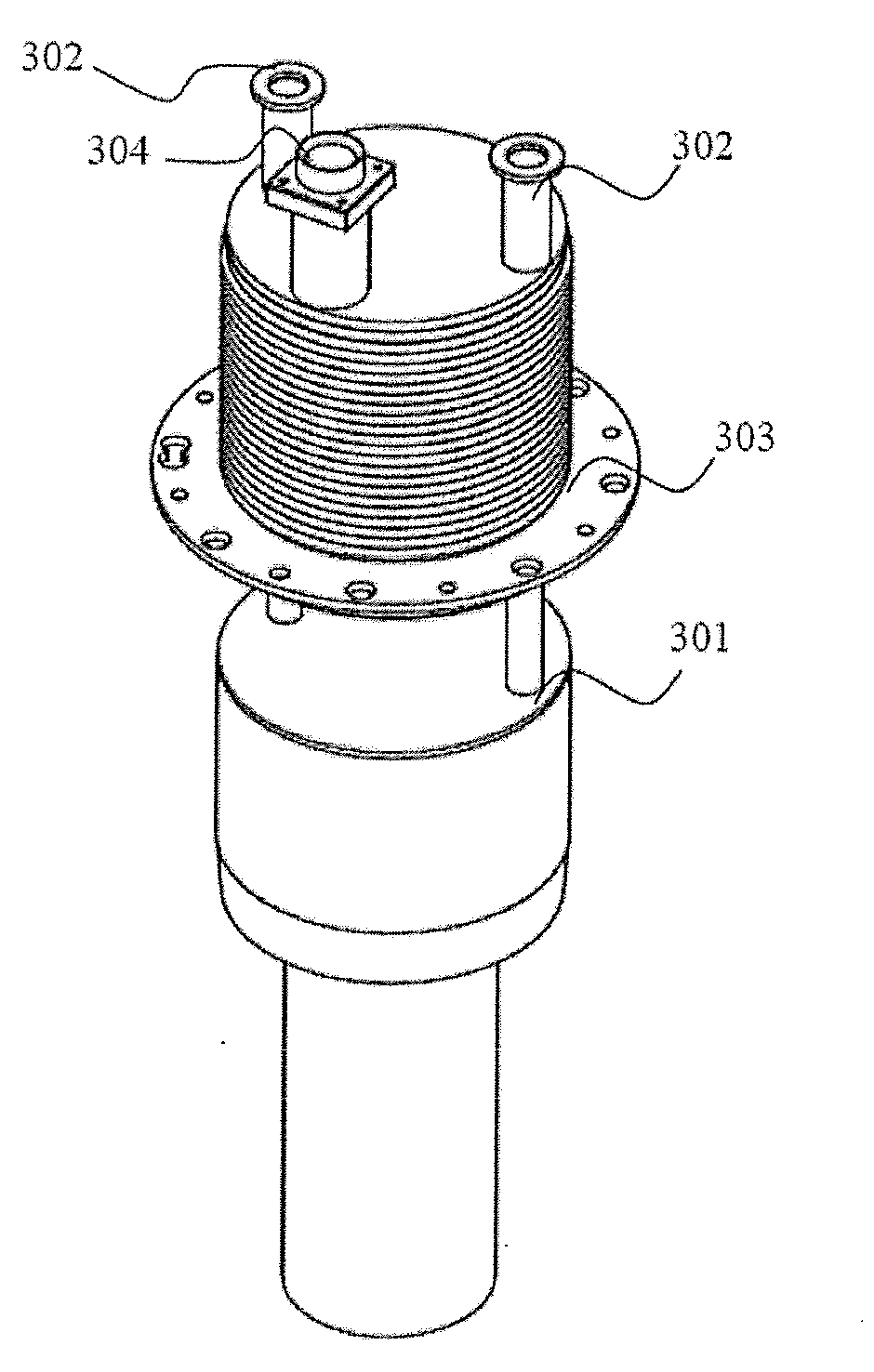
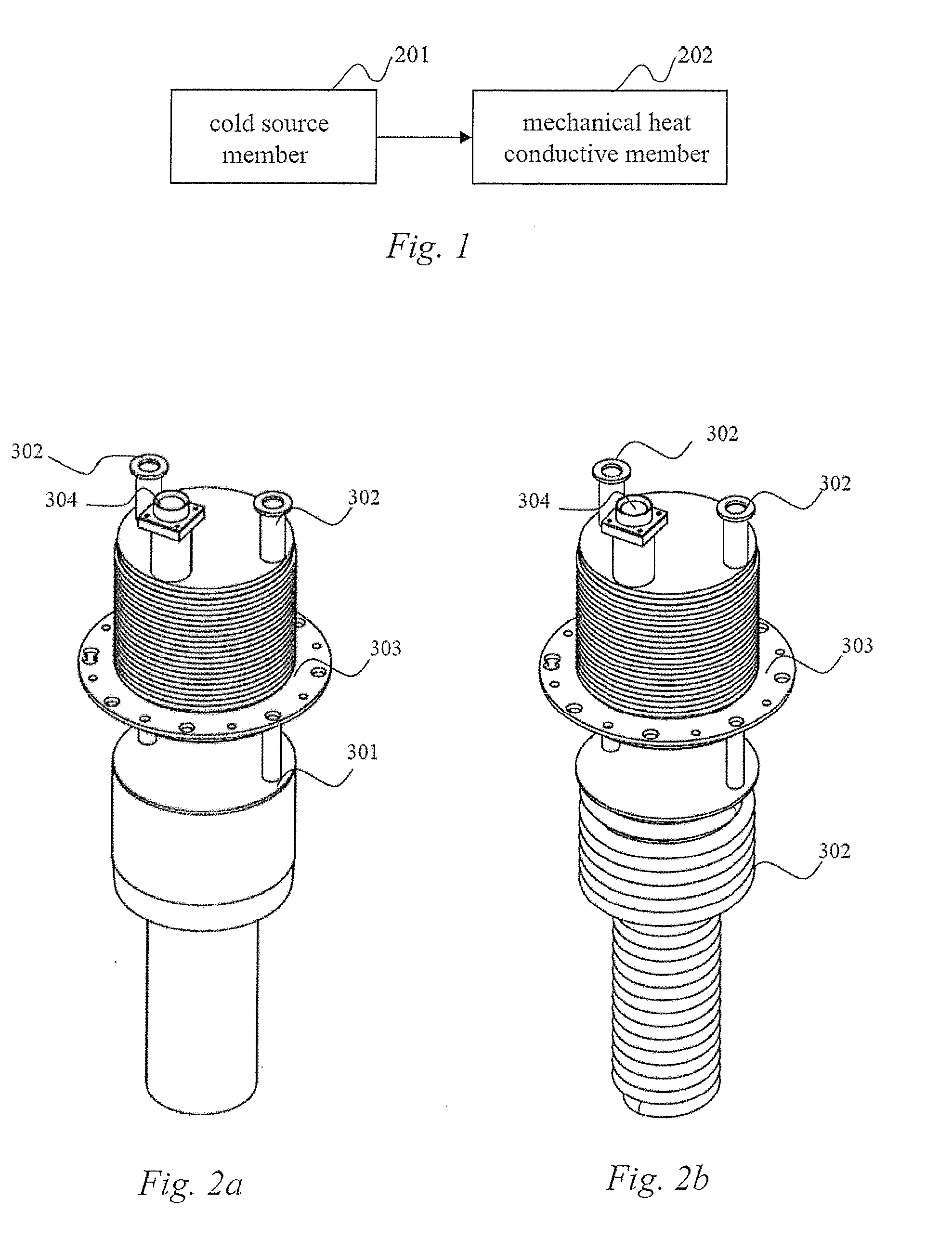
[0019]According to another embodiment, the step of actively cooling down the thermal radiation shield using the mechanical refrigerator includes making a heat conducting member of the mechanical refrigerator into a mechanical heat conductive member in coordination with the structure of a cold head apron in the superconducting magnet, fixing the mechanical heat conductive member into the apron, and starting the mechanical refrigerator to transfer cooling to the thermal radiation shield of the superconducting magnet via the mechanical heat conductive member and apron so as to actively cool the thermal radiation shield down to the second temperature.
[0021]It can be seen from the above embodiments that since the thermal radiation shield is actively cooled down to a second temperature before the second stage of precooling of the superconducting magnet in accordance with the present invention, and the second temperature is below the temperature of the thermal radiation shield after the first stage of precooling of the superconducting magnet, when the second stage of precooling is carried out on the superconducting magnet, the radiation heat of the thermal radiation shield that proceeds the cryogen vessel can be reduced, the consumption of cryogen (such as liquid helium) can be reduced during open-loop refrigeration, and the refrigeration speed can be increased during closed-loop refrigeration.

Problems solved by technology

However, since the temperature difference between the exterior of the vacuum chamber and the interior of the cryogen vessel is relatively large, too much thermal radiation heat exists between the vacuum chamber and the cryogen vessel, so that in order to reduce the radiation heat between the vacuum chamber and the cryogen vessel, a thermal radiation shield is generally provided between the vacuum chamber and the cryogen vessel.

Method used


Image

  • Precooling device, superconducting magnet and magnetic resonance imaging apparatus
  • Precooling device, superconducting magnet and magnetic resonance imaging apparatus

Examples


Embodiment Construction

[0024]In order to make the object, technical solutions and advantages of the present invention more apparent, the present invention will be further described in detail below by means of embodiments.

[0025]In the background art to which the aforementioned British patent application GB2433581A relates, first of all, a superconducting magnet is cooled down to a first temperature using liquid nitrogen, and at this time the thermal radiation shield is cooled from 300 K down to about 200 K, but when the superconducting magnet is cooled down to the operating temperature using liquid helium, the thermal radiation shield is still at the relatively high temperature of 200 K, i.e. it still has relatively high radiation heat onto the cryogen vessel. Therefore, when the thermal radiation shield is cooled from 200 K down to 50 K, it is necessary to evaporate plenty of liquid helium; however, the price of such liquid helium cryogen is very high, and it is very difficult to obtain a sufficient suppl...


PUM


Abstract

A precooling device for a thermal radiation shield of a superconducting magnet has a mechanical heat conductive member in contact with the thermal radiation shield of a superconducting magnet, for cooling the thermal radiation shield down to a second temperature before the second stage of precooling of the superconducting magnet, this second temperature being below the temperature of the thermal radiation shield after a first stage of precooling of the superconducting magnet. A superconducting magnet and magnetic resonance imaging equipment embody such a precooling device. The precooling device reduces the external radiation heat onto a cryogen vessel, thereby reducing the consumption of cryogen.

Description

BACKGROUND OF THE INVENTION[0001]1. Field of the Invention[0002]The present invention relates to precooling technology for superconducting magnets and, particularly, to a precooling device for a thermal radiation shield of a superconducting magnet, a superconducting magnet comprising the precooling device, and a magnetic resonance imaging apparatus embodying such a superconducting magnet.[0003]2. Description of the Prior Art[0004]Devices that are required to be cryogenically refrigerated, such as the superconducting coil of a superconducting magnet in magnetic resonance imaging (MRI) equipment, are generally placed in a cryogen vessel, the cryogen vessel is placed in an external vacuum chamber, and the space between the vacuum chamber and the cryogen vessel is evacuated, which provides effective heat insulation for the cryogen vessel. However, since the temperature difference between the exterior of the vacuum chamber and the interior of the cryogen vessel is relatively large, too m...

Claims


Application Information

Patent Timeline
IPC IPC(8): F28F7/00F25D31/00H01F6/04G01R33/28F28F1/10H01F6/00F25B19/00
CPCG01R33/3802H01F6/04G01R33/3804
Inventor FANG, ZHI CHUNYANG, LEI
Owner SIEMENS AG
Why Eureka
Try Eureka