
Water-vapor-permeable membrane, hollow-fiber membrane, and hollow-fiber membrane module

a technology of hollow fiber membrane and permeable membrane, which is applied in the direction of membranes, heating types, separation processes, etc., can solve the problems of low heat resistance, poor water vapor permeability, and high cost of hollow fiber membranes, and achieve low air leakage and high water vapor permeability

Active Publication Date: 2012-07-12
TORAY IND INC
View PDF11 Cites 15 Cited by
  • Summary
  • Abstract
  • Description
  • Claims
  • Application Information

AI Technical Summary

Benefits of technology

The present invention provides water vapor permeable membranes with high water vapor permeability and low air leakage. These membranes can be used to produce hollow fiber membranes and modules that can resist high flow volumes of air while maintaining high water vapor permeability. These membranes can be used in humidifiers of fuel cell systems.

Problems solved by technology

However, it has the disadvantage of poor water vapor permeability.
However, they are not high enough in water vapor permeability to serve practically as hollow fiber membrane for humidification, and they are also low in heat resistance.
Furthermore, the hollow fiber membranes themselves will be very expensive.
In any case, the existing hollow fiber membranes for humidification are intended to have good gas barrier properties, but accordingly they are poor in water vapor permeability, failing to serve adequately as material for humidification.
It is described, however, that the hollow fiber membrane thus produced is intended to serve as ultrafiltration membrane for oily water separation, and therefore, it is not designed for water vapor permeation.
However, this hollow fiber membrane cannot achieve sufficient humidification performance.
However, such an asymmetric structure alone cannot act to develop a sufficient water vapor permeability and will fail to achieve a high humidification performance.
The method proposed in Patent document 4 actually can protect part of the hollow fibers by covering the hollow fibers with textured yarns, but it is difficult to increase the strength sufficiently to resist a high flow volume of 4,000 NL / min.
In the method proposed in Patent document 5, high-strength rods act too strongly to restrain the gas flow into hollow fibers, leading to performance problems such as inefficient water vapor permeation.
This method is difficult to carry out in an in-line step in the hollow fiber membrane production process, making it necessary to wind the hollow fiber membranes around the high-strength rod in an off-line step, which requires very lengthy operations.
Therefore, it is not suitable for a step that handles several thousands to several tens of thousands of hollow fiber membranes.
This method, however, uses a low-stretchability support yarn passing through the center of a bundle of hollow fiber membranes, which fail to achieve a sufficient resistance to the high flow volume of gas in humidifiers.

Method used

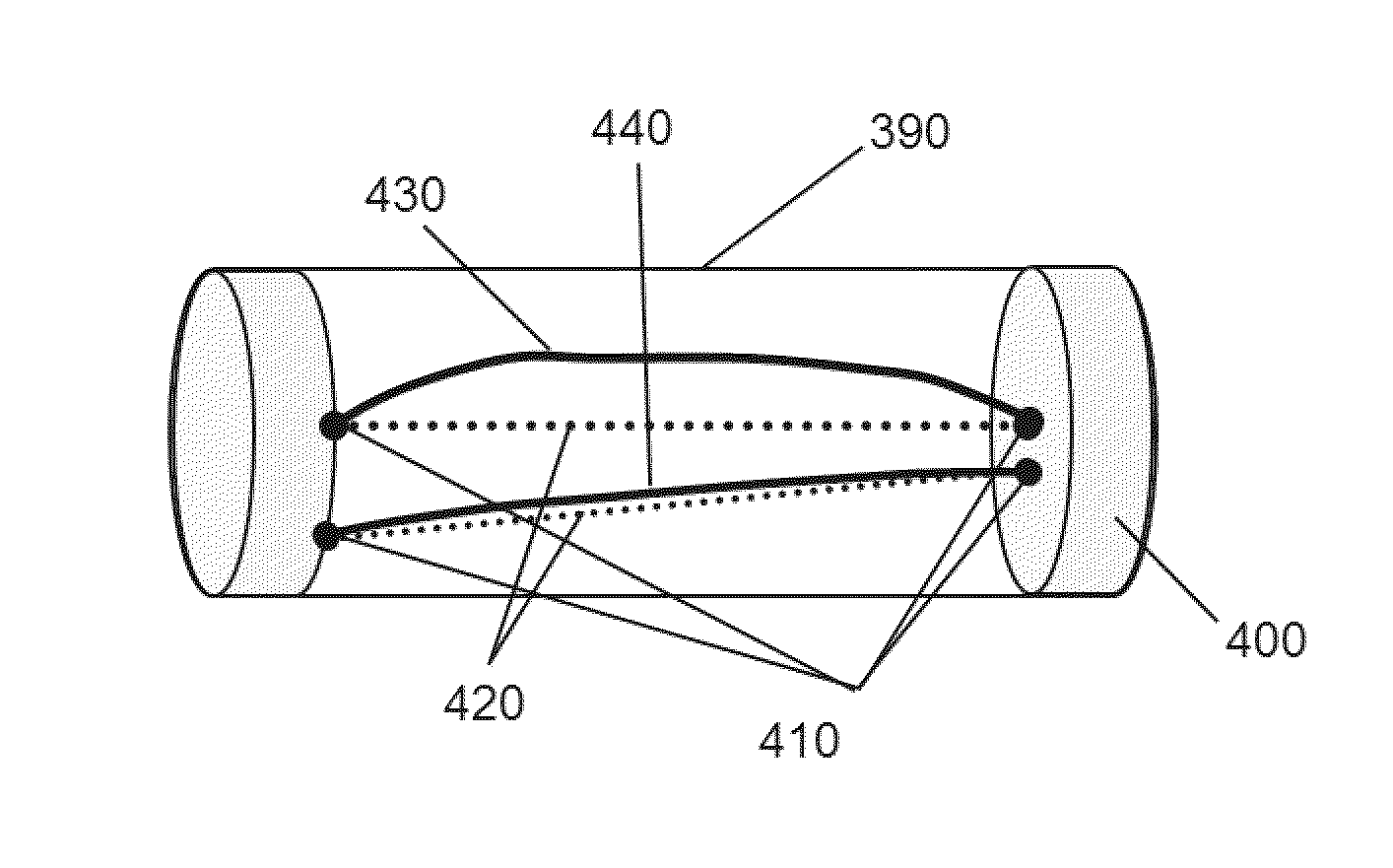
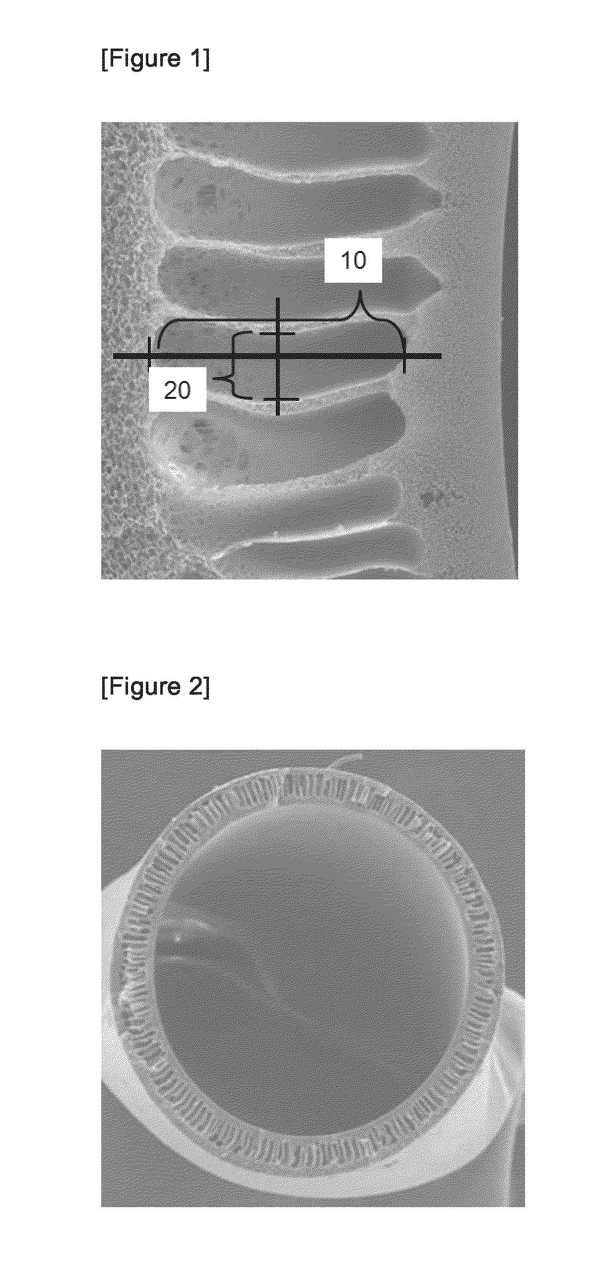
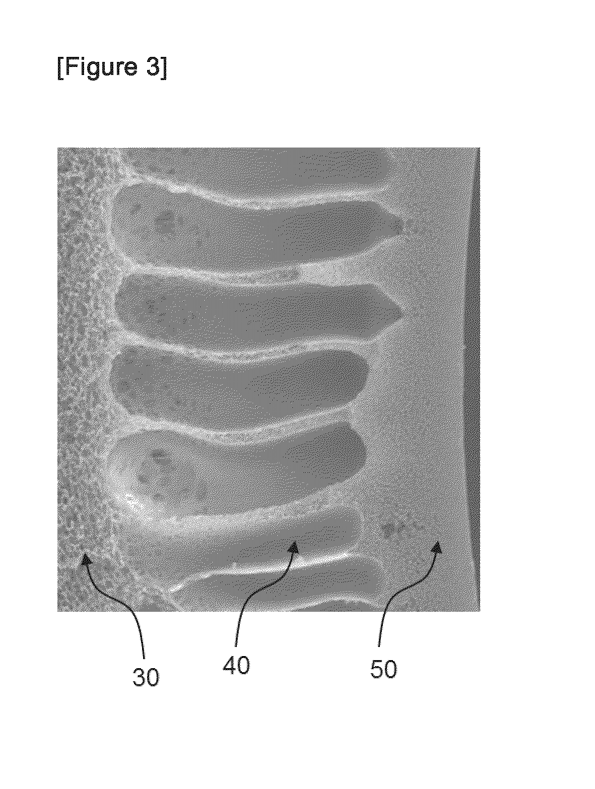

Image

  • Water-vapor-permeable membrane, hollow-fiber membrane, and hollow-fiber membrane module
  • Water-vapor-permeable membrane, hollow-fiber membrane, and hollow-fiber membrane module
  • Water-vapor-permeable membrane, hollow-fiber membrane, and hollow-fiber membrane module

Examples


example 1

[0124]A raw material solution for membrane production consisting of 16 parts of polysulfone resin (P3500, supplied by Solvay), 6 parts of polyvinyl pyrrolidone (K30, supplied by ISP), 3 parts of polyvinyl pyrrolidone (K90, supplied by ISP), 74 parts of dimethyl acetamide, and 1 part of water was dissolved at 90° C. and maintained at 50° C. A core liquid consisting of 40 parts of dimethyl acetamide and 60 parts of water was prepared. The raw material solution for membrane production and the core liquid were discharged simultaneously from the outer and the inner tube, respectively, of a bicylindrical nozzle with an outside diameter of 1.0 mm and an inside diameter of 0.7 mm. The discharged liquid was passed through a 350 mm dry-air portion at a temperature of 30° C., followed by being immersed in a coagulation bath at 40° C. consisting of 90 parts of water and 10 parts of dimethyl acetamide. At this point, the viscosity of the raw material solution for membrane production was 18 poise...

example 2

[0128]A raw material solution for membrane production consisting of 18 parts of polysulfone resin (P3500, supplied by Solvay), 9 parts of polyvinyl pyrrolidone (K30, supplied by ISP), 72 parts of dimethyl acetamide, and 1 part of water was dissolved at 90° C. and maintained at 50° C. A core liquid consisting of 40 parts of dimethyl acetamide and 60 parts of water was prepared. The raw material solution for membrane production and the core liquid were discharged simultaneously from the outer and the inner tube, respectively, of a bicylindrical nozzle with an outside diameter of 1.0 mm and an inside diameter of 0.7 mm. The discharged liquid was passed through a 350 mm dry-air portion at a temperature of 30° C., followed by being immersed in a coagulation bath at 40° C. consisting of 90 parts of water and 10 parts of dimethyl acetamide. At this point, the viscosity of the raw material solution for membrane production was 11 poise. Subsequently, the coagulated hollow fiber membrane was ...

example 3

[0132]The raw material solution for membrane production prepared by dissolving materials in Example 2 was maintained at 50° C. A core liquid consisting of 60 parts of dimethyl acetamide and 40 parts of water was prepared. The raw material solution for membrane production and the core liquid were discharged simultaneously from the outer and the inner tube, respectively, of a bicylindrical nozzle with an outside diameter of 1.0 mm and an inside diameter of 0.7 mm. The discharged liquid was passed through a 350 mm dry-air portion at a temperature of 30° C., followed by being immersed in a coagulation bath at 40° C. consisting of 90 parts of water and 10 parts of dimethyl acetamide. Subsequently, the coagulated hollow fiber membrane was rinsed in a water bath at 80° C. and the hollow fiber membrane still in a wet state was wound up on a reel. The membrane production speed in this step was 18 m / min and the hollow fiber membrane had an inside diameter of 660 μm, a membrane thickness of 90...


PUM

PropertyMeasurementUnit
thicknessaaaaaaaaaa
thicknessaaaaaaaaaa
lengthaaaaaaaaaa

Abstract

A water vapor permeable membrane is provided comprising a dense layer and a support layer that are adjacent to each other, wherein the dense layer contains voids with a void length of 0.1 μm or less and the dense layer has a thickness of 0.1 μm or more and 2 μm or less while in the support layer, void (a), i.e. the void with the largest length in the 2 μm thick region measured from the boundary between the dense layer and the support layer into the support layer, has a length of 0.3 μm or more and void (b), i.e. the void with the largest length in the region ranging between 2 μm and 4 μm measured from the boundary into the support layer, has a length of 0.5 μm or more, the length of the void (b) being larger than that of the void (a). A water vapor permeable membrane having both a high water vapor permeability and a low air leakage is provided.

Description

CROSS REFERENCE TO RELATED APPLICATIONS[0001]This application is the U.S. National Phase application of PCT International Application No. PCT / JP2009 / 064612, filed Aug. 21, 2009, the disclosure of which is incorporated herein by reference in its entirety for all purposes.FIELD OF THE INVENTION[0002]The invention relates to a water vapor permeable membrane, a water vapor permeable, hollow fiber membrane that is produced from this water vapor permeable membrane, and a hollow fiber membrane module produced from this hollow fiber membrane. More specifically, the invention relates to a water vapor permeable membrane, a hollow fiber membrane, and a hollow fiber membrane module that are used favorably in humidifiers of fuel cell systems.BACKGROUND OF THE INVENTION[0003]In recent years, increasing attention is attracted to the use of a water vapor permeable membrane for humidification or dehumidification. These humidifiers and dehumidifiers incorporating a water vapor permeable membrane have...

Claims


Application Information

Patent Timeline
Patent Type & Authority Applications(United States)
IPC IPC(8): B01D69/08B01D63/04B01D69/10
CPCB01D65/10B01D69/08B01D2325/02B01D2325/24B01D2325/40F24F2003/1435H01M8/04149Y02E60/50F24F6/00B01D61/363B01D2325/02834B01D61/36B01D63/02B01D69/082F24F6/04B01D69/10B01D69/1213B01D2325/022B01D2325/02833B01D2325/04B01D2325/025B01D2325/20
Inventor OSABE, MASAHIROTANAKA, KAZUMISUGAYA, HIROYUKI
Owner TORAY IND INC
Learn More