
Ear protector with a sound damping filter, sound damping filter for such an ear protector as well as method for manufacturing a sound damping filter for such an ear protector

a technology of filter and ear protector, which is applied in the field of ear protectors with a sound filter, can solve the problems of low surface energy, inconvenient, and inability to prevent water from entering the ear canal,

Active Publication Date: 2014-04-08
DYNAMIC EAR
View PDF32 Cites 2 Cited by
  • Summary
  • Abstract
  • Description
  • Claims
  • Application Information

AI Technical Summary

Benefits of technology

The patent describes an ear protector that prevents water from getting inside and ruining the hearing. The protection is made of a special material that allows air and water vapor to flow through it. This material helps to control the damping of the sound, which can improve the overall quality of the ear protectors.

Problems solved by technology

However, this known ear protector with its perforated membrane cannot prevent penetration of water in the ear canal and is not suitable for example for people with openings in the eardrum.
The microscopic pores of this known ear protector that let air and water vapour pass through, yet have such low surface energy that the surface tension of any (liquid) water in contact remains too high to allow it to squeeze through the pores.
Microporous membranes have traditionally been let down by the contamination of their pores which significantly degrades the moisture transfer through the membrane and commonly also have poorer adhesion to fabrics making them more susceptible to de-lamination.

Method used


Image

  • Ear protector with a sound damping filter, sound damping filter for such an ear protector as well as method for manufacturing a sound damping filter for such an ear protector
  • Ear protector with a sound damping filter, sound damping filter for such an ear protector as well as method for manufacturing a sound damping filter for such an ear protector
  • Ear protector with a sound damping filter, sound damping filter for such an ear protector as well as method for manufacturing a sound damping filter for such an ear protector

Examples


second embodiment

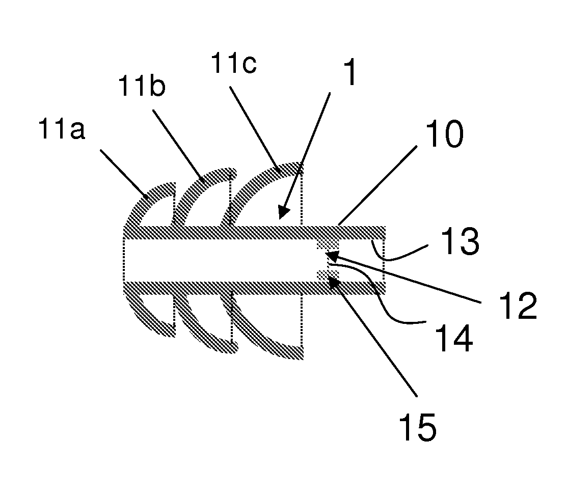
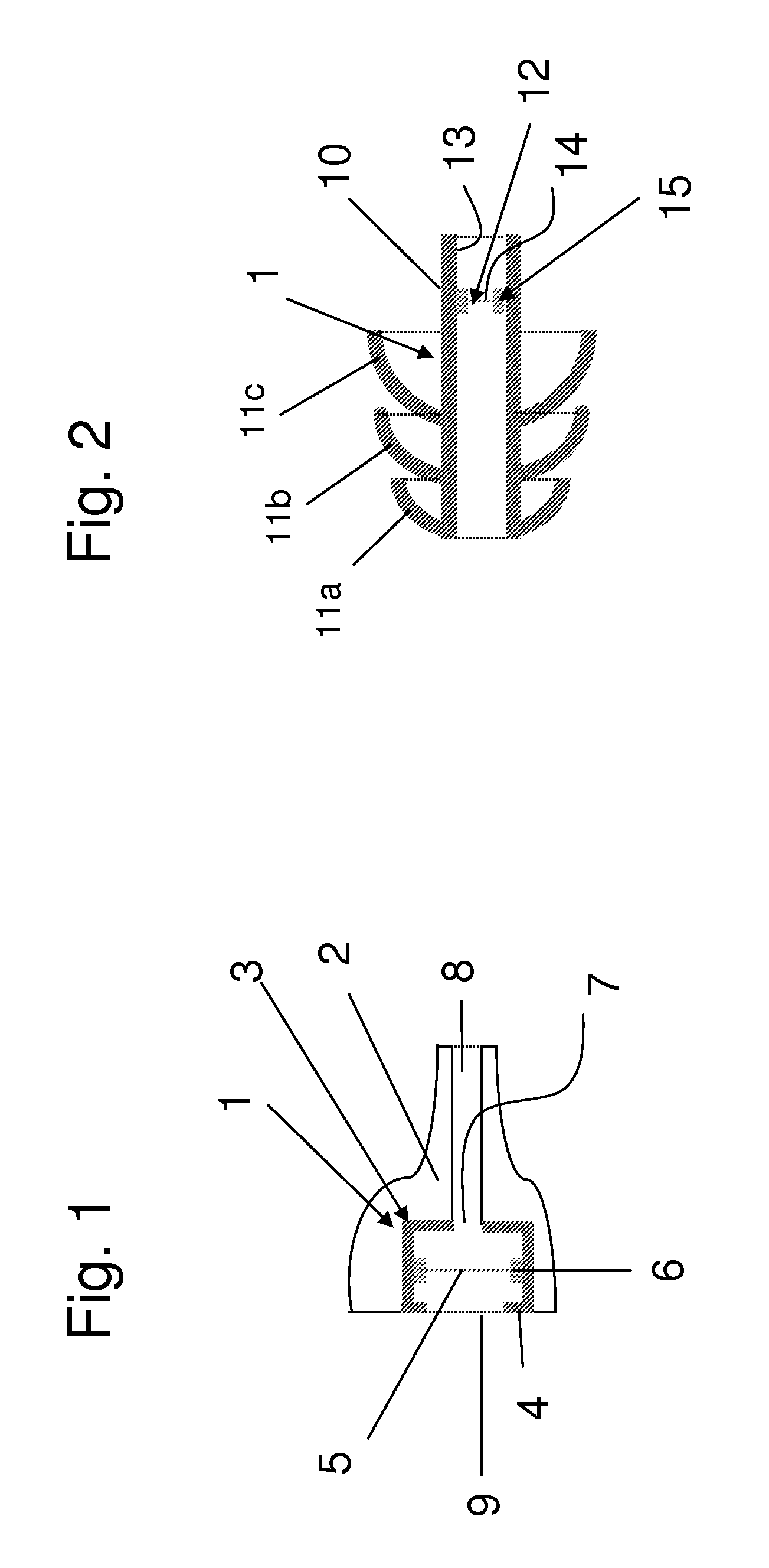
[0025]In FIG. 2 is shown the ear protector 1, comprising a universal earpiece 10 that is sealed to the ear by means of three flanges 11a, 11b and 11c. In the ear protector a sound damping filter 12 is mounted, comprising a sound channel 13, which also is a filter housing for a membrane 14, mounted on a membrane support 15. The membrane 14 is composed of a non-porous material with same composition and same “breathability” characteristics as the membrane 5 in FIG. 1.

third embodiment

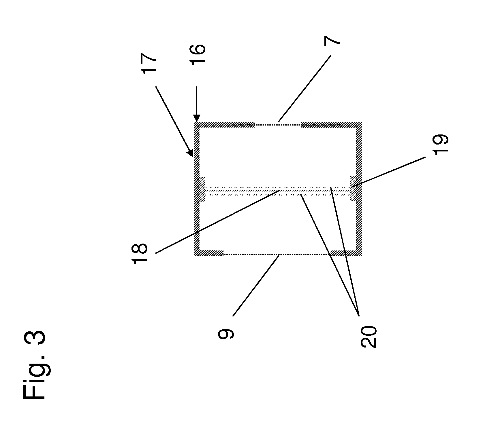
[0026]FIG. 3 shows in the ear protector 1 a sound damping filter 16 with a filter housing 17 comprising a membrane 18, mounted on a membrane support 19. The membrane 18 is composed of a non-porous material with same composition and same “breathability” characteristics as the membrane 5 in FIG. 1. This filter housing 17 has same dimensions and characteristics as the filter housing 4 and is mounted in the custom earpiece 2. The support 19 carries membrane deflection limiters 20, located at both sides of the membrane 18, each comprising an impulse blocker mesh. This support 19 has standardized dimensions and is mounted in the sound channel 7 of the ear protector, connecting the inside 8 and outside 9 of the of the ear protector. These impulse blocker mesh are limiting the deflections of the membrane due to overpressure and under-pressure in the sound channel. This limitation of the deflection stops a pressure wave in the sound channel 7 on an effective way.

[0027]In an alternative of th...


PUM

PropertyMeasurementUnit
sound attenuationaaaaaaaaaa
frequenciesaaaaaaaaaa
molecular strengthaaaaaaaaaa

Abstract

An ear protector (1) with a sound damping filter (3), comprises a membrane (5). The membrane is composed of a material that permits the transmission of air and water vapor with respect to the ear from the into the outside of the ear protector, the membrane is pre stressed mounted in the filter, enabling a bigger surface and hence bigger air and water transport at same sound attenuation.

Description

CROSS-REFERENCE TO RELATED APPLICATIONS[0001]This application is a U.S. National Stage application under 35 U.S.C. §371 of International Application PCT / NL2010 / 050827 (published as WO 2011 / 078659 A1), filed Dec. 7, 2010 which claims priority to Application NL 2004004, filed Dec. 22, 2009. Benefit of the filing date of each of these prior applications is hereby claimed. Each of these prior applications is hereby incorporated by reference in its entirety.FIELD OF INVENTION[0002]The invention relates to ear protectors with a sound filter.DESCRIPTION OF PRIOR ART[0003]The invention relates to an ear protector with a sound damping filter, comprising a membrane composed of a material for permitting the transmission of air with respect to the ear from the outside to the inside of the ear protector.[0004]Such an ear protector with sound damping filter is disclosed in EP 1 046 382 A1 and provides with its perforated membrane a ventilation of the ear canal. Ventilation of the ear canal is imp...

Claims


Application Information

Patent Timeline
Patent Type & Authority Patents(United States)
IPC IPC(8): A61F11/06H04R25/00H04R1/10
CPCA61F2011/085A61F11/008A61F11/08A61F11/085A61F11/30
Inventor WILMINK, ENGBERT
Owner DYNAMIC EAR
Learn More