
Devices for reducing left atrial pressure, and methods of making and using same

a technology of left atrial pressure and devices, applied in the field of devices and methods for reducing left atrial pressure, can solve the problems of enlarging the heart chamber, enlarging the ventricle, and insufficient cardiac output to meet the needs of the body, so as to reduce the left atrial pressure, relieve pulmonary congestion, and increase cardiac outpu

Active Publication Date: 2012-06-28
WAVE LTD V
View PDF1 Cites 130 Cited by
  • Summary
  • Abstract
  • Description
  • Claims
  • Application Information

AI Technical Summary

Benefits of technology

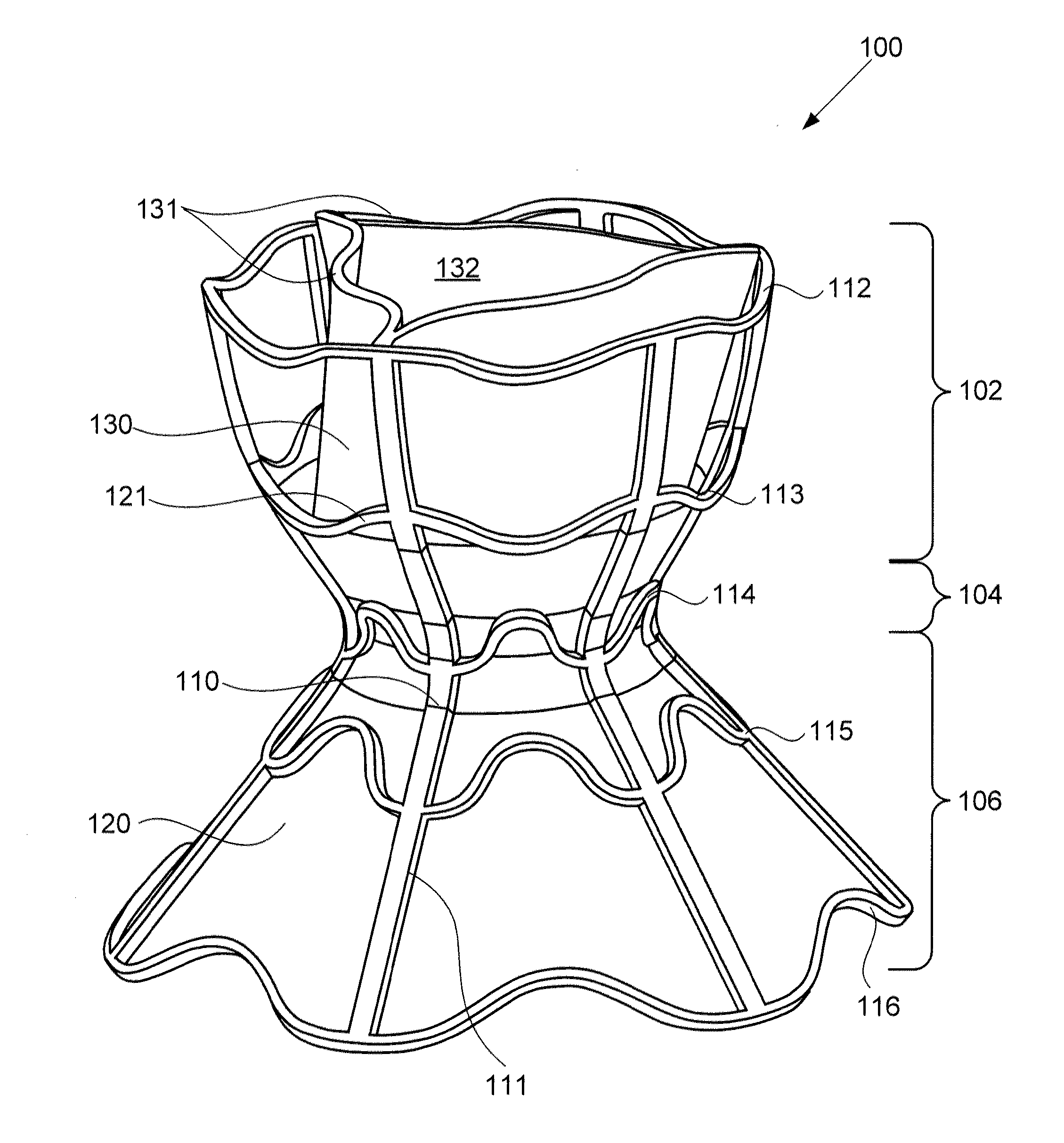
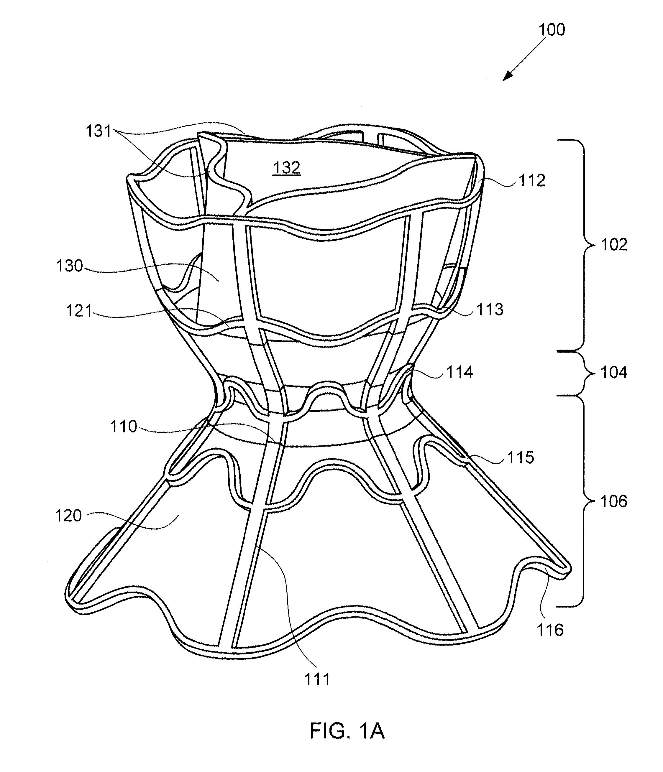
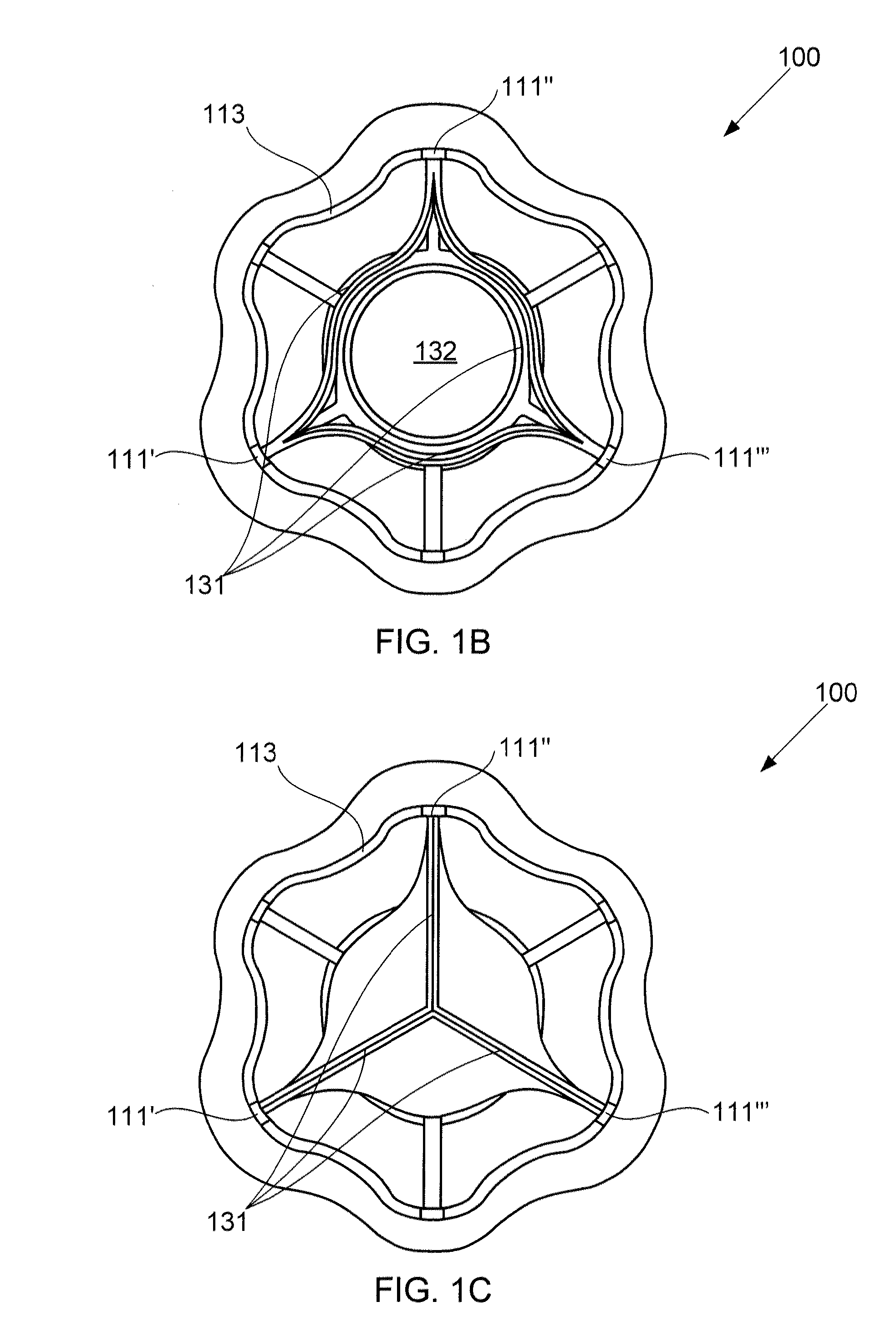
[0014]Embodiments of the present invention provide hourglass-shaped devices for reducing left atrial pressure, and methods of making and using the same. As elaborated further herein, such reductions in left atrial pressure may increase cardiac output, relieve pulmonary congestion, and lower pulmonary artery pressure, among other benefits. The inventive devices are configured for implantation through the atrial septum, and particularly through the middle of the fossa ovalis, away from the surrounding limbus, inferior vena cava (IVC), and atrial wall. The devices are configured to provide one-way blood flow from the left atrium to the right atrium when the pressure in the left atrium exceeds the pressure in the right atrium, and thus decompress the left atrium. Such a lowering of left atrial pressure may offset abnormal hemodynamics associated with CHF, for example, to reduce congestion as well as the occurrence of acute cardiogenic pulmonary edema (ACPE), which is a severe manifestation of CHF in which fluid leaks from pulmonary capillaries into the interstitium and alveoli of the lung. In particular, lowering the left atrial pressure may improve the cardiac function by:
[0015](1) Decreasing the overall pulmonary circulation pressure, thus decreasing the afterload on the heart,
[0016](2) Increasing cardiac output by reducing left ventricular end systolic dimensions, and

Problems solved by technology

Heart failure is the physiological state in which cardiac output is insufficient to meet the needs of the body and the lungs.
However, the larger volume of blood also stretches the heart muscle, enlarging the heart chambers, particularly the ventricles.
At a certain amount of stretching, the heart's contractions become weakened, and the heart failure worsens.
In low ejection fraction (EF) heart failure, high pressures in the heart result from the body's attempt to maintain the high pressures needed for adequate peripheral perfusion.
However, the heart weakens as a result of the high pressures, aggravating the disorder.
Pressure in the left atrium may exceed 25 mmHg, at which stage, fluids from the blood flowing through the pulmonary circulatory system flow out of the interstitial spaces and into the alveoli, causing pulmonary edema and lung congestion.
This stiffness may impede blood from filling the heart, and produce backup into the lungs, which may result in pulmonary venous hypertension and lung edema.
Such mechanical devices enable propulsion of significant volumes of blood (liters / min), but are limited by a need for a power supply, relatively large pumps, and the risk of hemolysis, thrombus formation, and infection.
In addition to cardiac transplant, which is highly invasive and limited by the ability of donor hearts, surgical approaches such as dynamic cardiomyoplastic or the Batista partial left ventriculectomy may also be used in severe cases.
However, Dobak states that a valved design may not be optimal due to a risk of blood stasis and thrombus formation on the valve, and that valves can also damage blood components due to turbulent flow effects.
Dobak does not provide any specific guidance on how to avoid such problems.

Method used


Image

  • Devices for reducing left atrial pressure, and methods of making and using same
  • Devices for reducing left atrial pressure, and methods of making and using same
  • Devices for reducing left atrial pressure, and methods of making and using same

Examples


example

[0091]An exemplary device 800 such as described above with respect to FIGS. 8A-8C was implanted into four sheep with induced chronic heart failure (V1-V4), while four sheep with induced chronic heart failure did not receive the device, and were used as a control (C1-C4). An additional control animal was subjected to only a partial heart failure protocol, and did not receive the device (S1).

[0092]Chronic heart failure was induced in animals C1-C4 and V1-V4, who were less than 1 year of age and weighed between 70 and 120 pounds, by first anesthetizing the animals via a venous catheter positioned in a peripheral vessel, i.e., the ear. The animals were given an opiate or synthetic opiate (e.g., morphine or butorphanol) intravenously at 0.25 to 0.5 mg / kg, as well as telazol at 0.3 mg / kg, through the venous catheter, and anesthetized by intravenous etomidate. Anesthesia was maintained with 1.5% isoflurane delivered in 100% O2, via a tracheal tube. The animals were placed on a fluoroscope ...


PUM

PropertyMeasurementUnit
lengthaaaaaaaaaa
lengthaaaaaaaaaa
heightaaaaaaaaaa

Abstract

A device for regulating blood pressure between a patient's left atrium and right atrium comprises an hourglass-shaped stent comprising a neck region and first and second flared end regions, the neck region disposed between the first and second end regions and configured to engage the fossa ovalis of the patient's atrial septum; and a one-way tissue valve coupled to the first flared end region and configured to shunt blood from the left atrium to the right atrium when blood pressure in the left atrium exceeds blood pressure in the right atrium. The inventive devices may reduce left atrial pressure and left ventricular end diastolic pressure, and may increase cardiac output, increase ejection fraction, relieve pulmonary congestion, and lower pulmonary artery pressure, among other benefits. The inventive devices may be used, for example, to treat subjects having heart failure, pulmonary congestion, or myocardial infarction, among other pathologies.

Description

CROSS-REFERENCE TO RELATED APPLICATIONS[0001]This application claims the benefit of U.S. Provisional Patent Application No. 61 / 425,792, filed Dec. 22, 2010 and entitled “Device and Method for Regulating Pressure in a Heart Chamber,” the entire contents of which are incorporated by reference herein. This application is also a continuation-in-part under 35 U.S.C. §120 of International Patent Application No. PCT / IL2010 / 000354, which claims the benefit of U.S. Provisional Patent Application Nos. 61 / 175,073, filed May 4, 2009 and 61 / 240,667, filed Sep. 9, 2009, the entire contents of each of which are incorporated by reference herein.FIELD OF THE INVENTION[0002]This application generally relates to devices and methods for reducing left atrial pressure, particularly in subjects with heart pathologies such as congestive heart failure (CHF) or myocardial infarction (MI).BACKGROUND OF THE INVENTION[0003]Heart failure is the physiological state in which cardiac output is insufficient to meet ...

Claims


Application Information

Patent Timeline
Patent Type & Authority Applications(United States)
IPC IPC(8): A61F2/24B29C65/72
CPCA61B2017/00575A61B2017/00592A61B2017/00597A61B2017/00606A61B2017/00623A61F2/2415A61F2230/0078A61F2230/001A61F2220/005A61F2220/0058A61F2220/0075A61F2230/005A61F2/2418A61B2017/1139A61B2017/00243A61F2/2412
Inventor NITZAN, YAACOVYACOBY, MENASHE
Owner WAVE LTD V
Learn More